Category: Arduino

Robb – Hallowuino

Skittish Feather

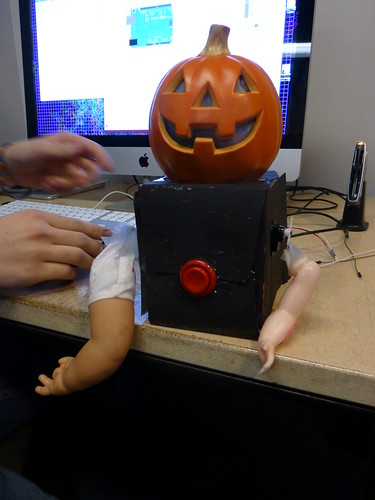
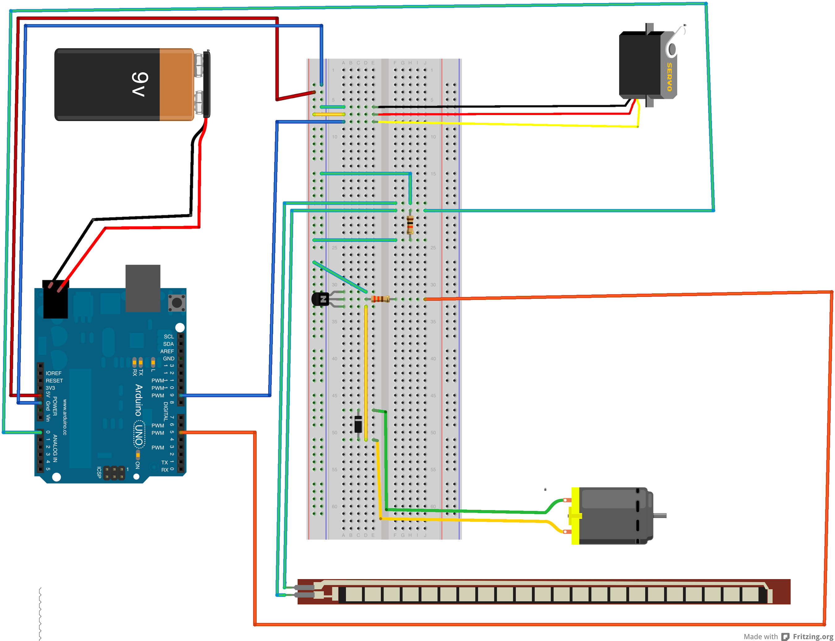
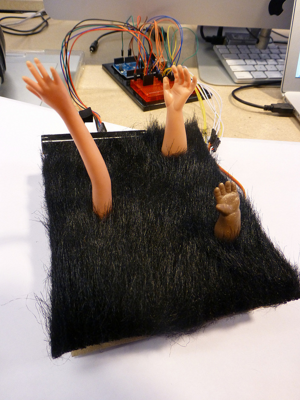
This piece consists of a proximity sensing feather which abruptly retracts into its box when a fleshy appendage gets too close.

I used this as a platform to explore humanizing mechanisms in mechanical systems as well as the capabilities of capacitive sensing. As such, I spent very little time on aesthetic and craft considerations and spent several long hours debugging and becoming comfortable with the CapSense library.
. The documentation was a little on the vague side in terms of actual performance and installation practices. Since presenting in class, I have learned that the presence of actual earth groundingdrastically improves the quality of the returned data. Various pins on the Arduino have vastly different ranges and responses, for which there is no documentation. A millimeter shift of wires can lead to enormous fluctuations in returned values. Ideally, all of the circuitry for this application would be done with immobile solid core wire.
The performance of Capacitive sensing on the Teensy 3.0 is much more stable and easier to implement. Unfortunately, hurricanes have put these boards in short supply.

[flickr video=8148331704 secret=135129d4b8 w=400 h=225]

//Thiers
#include 
#include 

CapSense cs = CapSense(2,13);  //RESISTOR, ANTENNA   //White,   yellow
Servo myservo;

//Mine

const int inDeg = 0;
const int outDeg = 60;

boolean out = true;
boolean touchClean = false;
boolean touch = false;
boolean lastTouch = false;
int pos;
long limit = 100;//set with a pot later
long reading;
long lastDebounceTime = 0;  // the last time the output pin was toggled
long debounceDelay = 111;    // the debounce time; increase if the output flickers


void setup()                    
{
  cs.set_CS_AutocaL_Millis(0xFFFFFFFF);     // turn off autocalibrate??
  Serial.begin(9600);
  myservo.attach(9);
  // cs.set_CS_Timeout_Millis(800);
}

void loop()                    
{
  limit=map(analogRead(0),0,1023,50,500);

 reading =  cs.capSense(40);

  /////// DeBugeRy //////

  Serial.print("Reading: ");
  Serial.print(reading);
  Serial.print("\t Pos: ");
  Serial.print(pos);
  Serial.print("\t limit: ");
  Serial.print(limit);
  Serial.print("\t Out: ");
  Serial.print(out);
  Serial.print("\t touchClean: ");
  Serial.print(touchClean);
  Serial.print("\t Touch: ");
  Serial.println(touch);
  //Serial saver delay
  delay(20);

  ////////InPuts  //////
if(out = true){
  if(reading>limit){
    touch = true;
  }
  else{ 
    touch = false;
  }
}

if (out = false){

    touch = false;
  }

  /// + Filtering + Debounce style ///////
  if (touch != lastTouch) {
    lastDebounceTime = millis();
  } 
  if ((millis() - lastDebounceTime) > debounceDelay) {
    touchClean = touch;
  }
  lastTouch = touch;


  //////Make the thwo connect///////
  if(touch){
    in();
    //out = false;

  }
  else {
    delay(100);
    outSlow();
    Serial.println("It's Out Now!");
  }

}
/////////// OuTpUtz /////////////

void in(){
  out = false;
  pos = inDeg;
  myservo.write(pos);
}


void outSlow(){
  Serial.print("outSlow Called!");

  while (pos<outDeg){
    pos = pos + 1;
    delay(22);
    myservo.write(pos);
    Serial.print(" * ");
  }
  Serial.println();
  out = true;

}

Hallowuino

I decided to make a mutant Baby Pumpkin Monster in celebration of Hallowuino. If you leave ze monster alone, it is a peaceful jack-o-latern. But, if you push his button, he will seek revenge. His eyes will switch from a yellow glow to flashing red, and his arms will swing with the intent to attack you.

mackenzie_1

If I were to put this piece in gallery, there would be a spooky night background behind it, and a metal link chain would be wrapped around it making it look as if it is being restrained. There would also be a sign next to it that reads: “Beware of Monster: DO NOT PUSH HIS BUTTON”. For some reason it is a natural instinct for people to rebel and press the button in this case, thus making the piece interactive.

Here is the video of my monster:

[flickr video=8148308678 secret=4d30222477 w=400 h=225]


Here is the Arduino Fritzing diagram of my monster:

Here is the code for my monster:

#include   // servo library
Servo servo1;  // servo control object
Servo servo2;  // servo control object

int redLED = 12;
int yelLED = 13;
const int buttonPin = 2;

//-----SCARY SETTINGS-----
int redEyeFlashTime = 75;
int motorCalls = 4;

void setup()
{
  pinMode(redLED,OUTPUT);
  pinMode(yelLED,OUTPUT);

  pinMode(buttonPin, INPUT);

  servo1.attach(9);
  servo2.attach(6);

  normalMode ();
}

void loop()
{
  //-----Check Button State-----
  int  buttonState = digitalRead(buttonPin);

  if (buttonState == LOW)
  {
    scaryMode();
  }
  else
  {
    normalMode();
  }
}

void normalMode ()
{
  digitalWrite(redLED, LOW);
  digitalWrite(yelLED, HIGH);
}

void scaryMode ()
{
  //-------SERVO CODE-------
  for(int i = 0; i < motorCalls; i++)
  {
    //int position1 = constrain(random(0, 180), 0, 180);
    int position1 = constrain(random(0, 180), 110, 180);
    servo1.write(position1);  // Move to next position

    int position2 = constrain(random(0, 180), 110, 180);
    servo2.write(position2);  // Move to next position

     //-------LED CODE----------
    digitalWrite(yelLED, LOW);
    digitalWrite(redLED, HIGH);

    delay(redEyeFlashTime);

    digitalWrite(redLED, LOW);

    //-------SERVO CODE-------
    position1 = constrain(random(0, 180), 0, 70);
    servo1.write(position1);  // Move to next position

    position2 = constrain(random(0, 180), 0, 70);
    servo2.write(position2);  // Move to next position

    delay(redEyeFlashTime);
  }
}

Stephanie Cheung – Hallowino

Description
My project was the coffin box that was activated when the lid was opened! A photoresistor inside detected the increased light levels and turned on three pulsing LEDs, a randomly jittering servo motor, and a continuously spinning gear motor.
I had two little skeleton toys and chains attached to the servo that would jiggle around when it moved, and there were two plastic spiders on the gear motor that circled each other on a web. The LEDs were diffused by the gauze spiderweb and two little ghost cutouts were entangled in it.

Picture

Fritzing

Video


Code

int led[] = {
  3,5,6}; 
int brightnessArray[] = {
  0,0,0};  
int fadeAmountArray[] = {
  5,3,8};

int prevSecond = 0; 

#include 
Servo servo;

const int sensorPin = 0;
int lightLevel, high = 0, low = 1023;

const int motorPin = 11;

void setup()  { 
  pinMode(motorPin, OUTPUT);

  servo.attach(9);
  Serial.begin(9600);

  int i;
  for (i=0; i<=2; i++){
    pinMode(led[i], OUTPUT);
  }
} 

void loop()  { 
  lightLevel = analogRead(sensorPin);
  lightLevel = map(lightLevel, 400, 900, 0, 255);
  lightLevel = constrain(lightLevel, 0, 255);
  Serial.println( lightLevel); 

  if (lightLevel<=125){
    for (int i=0; i<=2; i++){
      int magic[] = {
        (int) (128 + 127 * sin (millis()/400.0)), (int) (128 + 127 * sin (millis()/700.0)), (int) (128 + 127 * sin (millis()/1000.0))                  };
      analogWrite(led[i], magic[i]); 
      delay(1); 
    }

    int currSecond = millis()/600;
    if (currSecond != prevSecond){
      Serial.println( "Do something trigger!"); 
      int position; 
      position = random(180);
      servo.write(position);
    }
    prevSecond = currSecond; // last thing to do 

    analogWrite(motorPin, 100);
  }

  else{
    for(int i=0; i<=2; i++){
      analogWrite(led[i], LOW);
    }
  }
}

Michael Importico – HALLOWUINO!

 
#include  

// Create a servo "object", called servo1. Each servo object
// controls one servo (you can have a maximum of 12):

Servo servo1;
const int flexpin = 0; 
const int motorPin = 5;

void setup() 
{   
  Serial.begin(9600);
  servo1.attach(9);
  pinMode(motorPin, OUTPUT);
} 

void loop() 
{ 
  int motospeed;
  int flexposition;    // Input value from the analog pin.
  int servoposition;   // Output value to the servo.

  // Read the position of the flex sensor (0 to 1023):

  flexposition = analogRead(flexpin);

  servoposition = map(flexposition, 760, 938, 0, 180);
  servoposition = constrain(servoposition, 0, 180);
  motospeed = map(flexposition,760,930,0,255);
  servo1.write(servoposition);
  analogWrite(motorPin, motospeed);

  //serial sensor info
  Serial.print("sensor: ");
  Serial.print(flexposition);
  Serial.print("  servo: ");
  Serial.println(servoposition);
  delay(20);  // wait 20ms between servo updates
}
The guts of my Mummy
This was an exciting project.  I used one flex sensor, one motor and a servo.  The action is activated by "hurting the mummy" - this means bending him in places he does not want to bend.  This upsets the Mummy and as you hurt him, he begins to writhe in pain - flailing his arms as his head spins.

Oliver – Hallowuino!!

I decided to make a creepy doll arm “graveyard” where the ground is made of (fake) fur. Three plastic doll arms are connected to Servo motors, and they rotate at a speed controlled by a sliding potentiometer. If the potentiometer is at its lowest value, the arms twitch instead of rotating.

Photo:


Video:

[flickr video=8148299589 secret=8463568572 w=400 h=225]


Fritzing diagram:


Code:

 
#include Servo.h 
// WordPress will not allow the less than / greater than 
// symbols that normally go around Servo.h 

Servo servo1, servo2, servo3;
const int sensorPin = 0;
int sensorValue, delayTime, position;

void setup() {
  // servos are connected to pins 7, 8 and 9
  servo1.attach(9);
  servo2.attach(8);
  servo3.attach(7);
  Serial.begin(9600);
}

void loop() {
  sensorValue = analogRead(sensorPin);
  Serial.println (sensorValue); 
  moveServos();
}

void moveServos() {
  // rotate to 180 degrees
  for(position = 0; position = 0; position -= sensorValue) {       
    changePositions();         
  }
}

void changePositions() {
  // test for the sensor value as servo rotates to see if it should 
  // change speed
  sensorValue = analogRead(sensorPin);
  // map potentiometer values to speeds 1-7
  sensorValue = map(sensorValue, 0,900, 1,7);
  servo1.write(position);
  servo2.write(position);
  servo3.write(position);
  // test for delay time as servo rotates to see if it should 
  // switch to twitching
  delayTime = testDelayTime();
  delay(delayTime);  
}

int testDelayTime() {
  // if the potentiometer value is less than 2, switch to the 
  // twitching motion by setting delay time to zero
  if (sensorValue < 2) {
    delayTime = 0;
  }
  else {
    delayTime = 20;
  }
  return delayTime;
}

Assignment 09

Arduino controlled Silly String shooter

Hallowuino!

Due Wednesday, October 31: Use a 9V battery to create a standalone (i.e. not connected to the computer) Halloween prop. It can be part of a costume, or a modification of a commercially available decoration (if you wish). It should be spoooky!

Shoot a video of the object in action; post it on YouTube and embed it in a blog post with the category Assignment-09.

  • It should have at least one input: buttons, potentiometer, sensors….
  • It should have some kind of output: LEDs and/or servo, etc. etc.
  • It should work without a computer attached. Program the Arduino, unplug the USB and plug the 9V cable. You can press the tiny reset button to restart the program.
  • You can use alligator clips or wire extensions to separate Arduino + board from sensors and actuators.
  • You can check the examples in the manual, like the DC motor…
  • LEDs themselves are not that exciting, but you can use all sorts of objects to diffuse their light ping-pong balls, balloons, pumpkins…

Code Example:
Light sensor controlled twitchy servo. Servo twitches randomly when it gets dark.

#include <Servo.h> 
Servo servo1;
int pos1 = 0;
int period = 500;
int sensorValue = 0;
unsigned long lastDidItTime = 0;

void setup() { 
  servo1.attach(3);  // attaches the servo on pin 3 to the servo object 
  Serial.begin(9600);
} 

void loop() {
  sensorValue = analogRead(A0);
  unsigned long presentTime = millis();
  if(sensorValue < 90){  // if it's dark...
    unsigned long elapsedAmount = presentTime - lastDidItTime;
    if (elapsedAmount > period){  // do something spooky
      pos1 = random (0, 180); 
      servo1.write(pos1);
      lastDidItTime = presentTime;
    }
  }

}
Comments Off on Assignment 09 Posted in

Luo Yi Tan – Arduino assignment: KITT lights

No fading

int ledPins[] = {2,3,4,5,6,7, 8, 9};

void setup()
{
  int index;
  for(index = 0; index <= 7; index++)
  {
    pinMode(ledPins[index],OUTPUT);
  }
}

void loop() {
  int index;
  int delayTime = 50; 

  for(index = 7; index >= 0; index--)
  {
    digitalWrite(ledPins[index], HIGH);
    delay(delayTime);
    digitalWrite(ledPins[index], LOW);
  }  
}

Fading

int ledPins[] = {3, 5, 6, 9, 10, 11};

void setup()
{
  int index;
  for(index = 0; index <= 7; index++)
  {
    pinMode(ledPins[index],OUTPUT);
  }
}

void loop() {
  int index;
  int delayTime = 1; 
  int delayTime2 = 100; 
  for(int fadeValue = 255 ; fadeValue > 0; fadeValue -=5) {  
      analogWrite(ledPins[index], fadeValue);            
      delay(5);                            
    }    
  }

  for(index = 5; index >= 0; index--)
    for(int fadeValue = 255 ; fadeValue > 0; fadeValue -=5) { 
      analogWrite(ledPins[index], fadeValue);            
      delay(5);                            
    }    

}

Wished I had a better camera, my ipod doesn’t have widescreen :(

Oliver – First Two Arduino Assignments

Here’s my Night Rider video:

[youtube http://youtu.be/CiE3Men2INI]


// Oliver Haimson
// first Arduino assignment
// code modified from SIK Guide Circuit 1 code

int L1 = 13; // LED connected to digital pin 13
int L2 = 12; // LED connected to digital pin 12
int L3 = 11; // LED connected to digital pin 11
int L4 = 10; // LED connected to digital pin 10
int L5 = 9; // LED connected to digital pin 9
int L6 = 8; // LED connected to digital pin 8
int L7 = 7; // LED connected to digital pin 7
int L8 = 6; // LED connected to digital pin 6

void setup() {
// initialize the digital pin as an output:
pinMode(L1, OUTPUT);
pinMode(L2, OUTPUT);
pinMode(L3, OUTPUT);
pinMode(L4, OUTPUT);
pinMode(L5, OUTPUT);
pinMode(L6, OUTPUT);
pinMode(L7, OUTPUT);
pinMode(L8, OUTPUT);
}

void loop()
{
digitalWrite(L1, HIGH);
delay(50);
digitalWrite(L2, HIGH);
delay(100);
digitalWrite(L1, LOW);
delay(50);
digitalWrite(L3, HIGH);
delay(100);
digitalWrite(L2, LOW);
delay(50);
digitalWrite(L4, HIGH);
delay(100);
digitalWrite(L3, LOW);
delay(50);
digitalWrite(L5, HIGH);
delay(100);
digitalWrite(L4, LOW);
delay(50);
digitalWrite(L6, HIGH);
delay(100);
digitalWrite(L5, LOW);
delay(50);
digitalWrite(L7, HIGH);
delay(100);
digitalWrite(L6, LOW);
delay(50);
digitalWrite(L8, HIGH);
delay(50);
digitalWrite(L7, LOW);
delay(100);
digitalWrite(L8, LOW);
digitalWrite(L7, HIGH);
delay(100);
digitalWrite(L6, HIGH);
delay(100);
digitalWrite(L7, LOW);
delay(50);
digitalWrite(L5, HIGH);
delay(100);
digitalWrite(L6, LOW);
delay(50);
digitalWrite(L4, HIGH);
delay(100);
digitalWrite(L5, LOW);
delay(50);
digitalWrite(L3, HIGH);
delay(100);
digitalWrite(L4, LOW);
delay(50);
digitalWrite(L2, HIGH);
delay(100);
digitalWrite(L3, LOW);
delay(50);
digitalWrite(L1, HIGH);
digitalWrite(L2, LOW);
delay(50);
}

And here is my Potentiometer:

[youtube http://youtu.be/NH6dwHtnXhs]

Michael Importico – Arduino Knight Rider

Arduino Knight Rider LED from Michael Importico on Vimeo.

 
int sensorPin = 0;  //middle sensor wire on pot @ analog 0

int ledPin1 = 13; //LED connected digital pin
int ledPin2 = 12;
int ledPin3 = 11;
int ledPin4 = 10;
int ledPin5 = 9;
int ledPin6 = 8;

void setup(){
  pinMode(ledPin1, OUTPUT); //ledPin is a digital output at this pin
  pinMode(ledPin2, OUTPUT);
  pinMode(ledPin3, OUTPUT);
  pinMode(ledPin4, OUTPUT);
  pinMode(ledPin5, OUTPUT);
  pinMode(ledPin6, OUTPUT);
}
void loop(){
  int sensorValue; //an interger named sensorValue
  sensorValue = analogRead(sensorPin);//sets sensorValue to pot reading

  digitalWrite(ledPin1, HIGH);//turn on ledPin1
  delay(sensorValue);//wait time as set by pot
  digitalWrite(ledPin1, LOW);//turn off ledPin1
  delay(sensorValue);//wait time as set by pot

  digitalWrite(ledPin2, HIGH);
  delay(sensorValue);
  digitalWrite(ledPin2, LOW);
  delay(sensorValue);

  digitalWrite(ledPin3, HIGH);
  delay(sensorValue);
  digitalWrite(ledPin3, LOW);
  delay(sensorValue);

  digitalWrite(ledPin4, HIGH);
  delay(sensorValue);
  digitalWrite(ledPin4, LOW);
  delay(sensorValue);

  digitalWrite(ledPin5, HIGH);
  delay(sensorValue);
  digitalWrite(ledPin5, LOW);
  delay(sensorValue);

  digitalWrite(ledPin6, HIGH);
  delay(sensorValue);
  digitalWrite(ledPin6, LOW);
  delay(sensorValue);

  digitalWrite(ledPin5, HIGH);
  delay(sensorValue);
  digitalWrite(ledPin5, LOW);
  delay(sensorValue);

  digitalWrite(ledPin4, HIGH);
  delay(sensorValue);
  digitalWrite(ledPin4, LOW);
  delay(sensorValue);

  digitalWrite(ledPin3, HIGH);
  delay(sensorValue);
  digitalWrite(ledPin3, LOW);
  delay(sensorValue);

  digitalWrite(ledPin2, HIGH);
  delay(sensorValue);
  digitalWrite(ledPin2, LOW);
  delay(sensorValue);
}

Stephanie: Arduino blinking lights

Here are the lights for the Knight Rider assignment!


int led1 = 13;
int led2 = 12;
int led3 = 11;
int led4 = 10;
int led5 = 9;
int led6 = 8;

// the setup routine runs once when you press reset:
void setup() { 
// initialize the digital pin as an output.
pinMode(led1, OUTPUT); 
pinMode(led2, OUTPUT); 
pinMode(led3, OUTPUT);
pinMode(led4, OUTPUT);
pinMode(led5, OUTPUT);
pinMode(led6, OUTPUT);
}


void loop() {
digitalWrite(led1, HIGH);
delay(100); 
digitalWrite(led1, LOW);
delay(100); 

digitalWrite(led2, HIGH); 
delay(102); 
digitalWrite(led2, LOW); 
delay(100); 

digitalWrite(led3, HIGH); 
delay(104); 
digitalWrite(led3, LOW); 
delay(100); 

digitalWrite(led4, HIGH); 
delay(106); 
digitalWrite(led4, LOW); 
delay(100); 

digitalWrite(led5, HIGH); 
delay(108); 
digitalWrite(led5, LOW); 
delay(100); 

digitalWrite(led6, HIGH); 
delay(110); 
digitalWrite(led6, LOW); 
delay(100); 

digitalWrite(led5, HIGH); 
delay(112); 
digitalWrite(led5, LOW); 
delay(100); 

digitalWrite(led4, HIGH); 
delay(114); 
digitalWrite(led4, LOW); 
delay(100); 

digitalWrite(led3, HIGH); 
delay(116); 
digitalWrite(led3, LOW); 
delay(100); 

digitalWrite(led2, HIGH); 
delay(118); 
digitalWrite(led2, LOW); 
delay(100); 
}