Computational Preoccupations with Vases
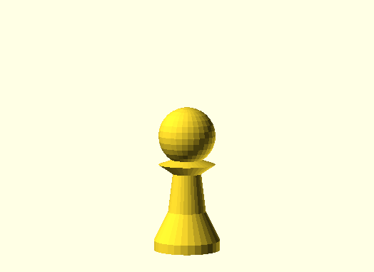
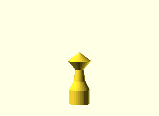
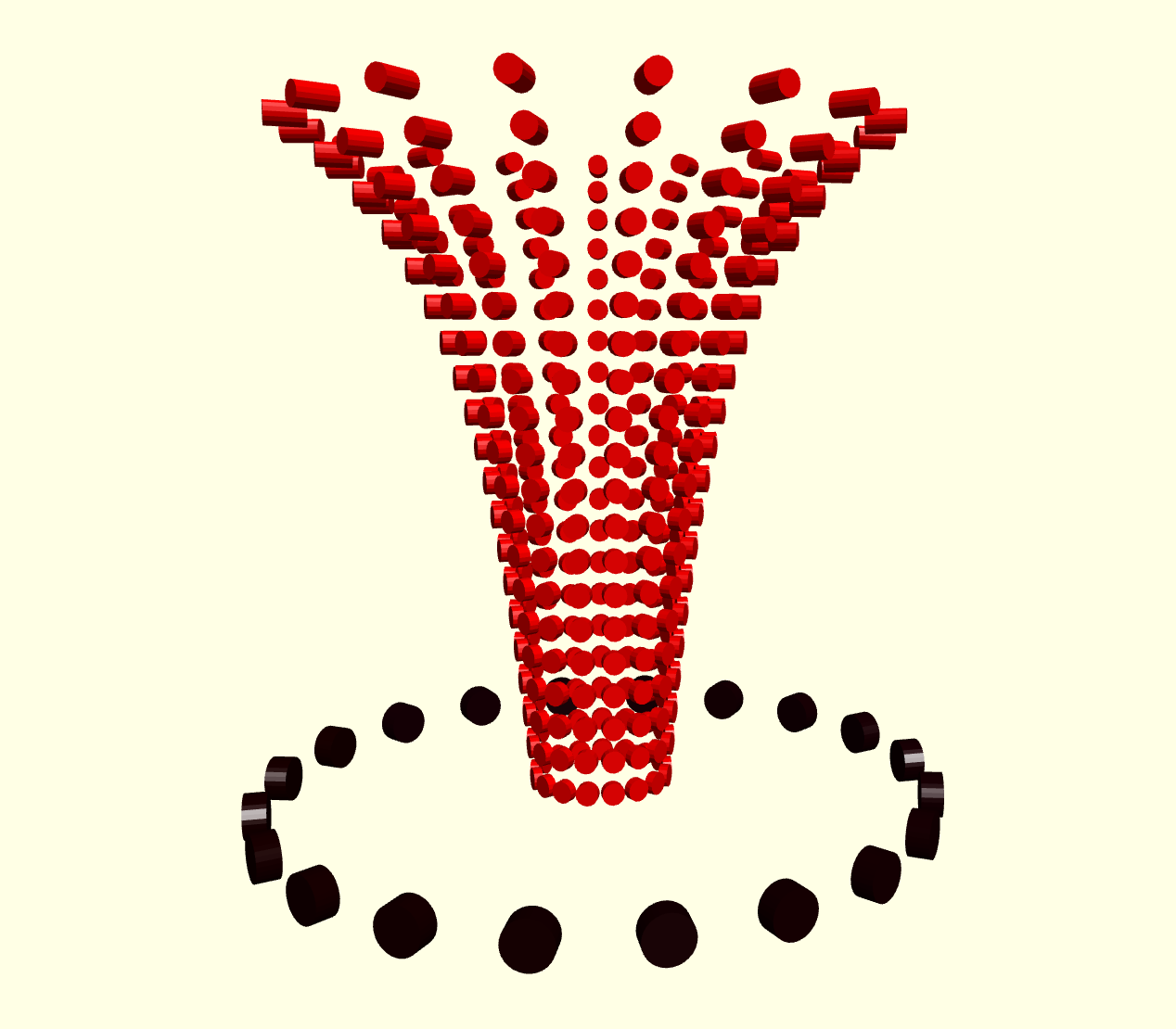
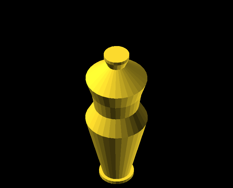
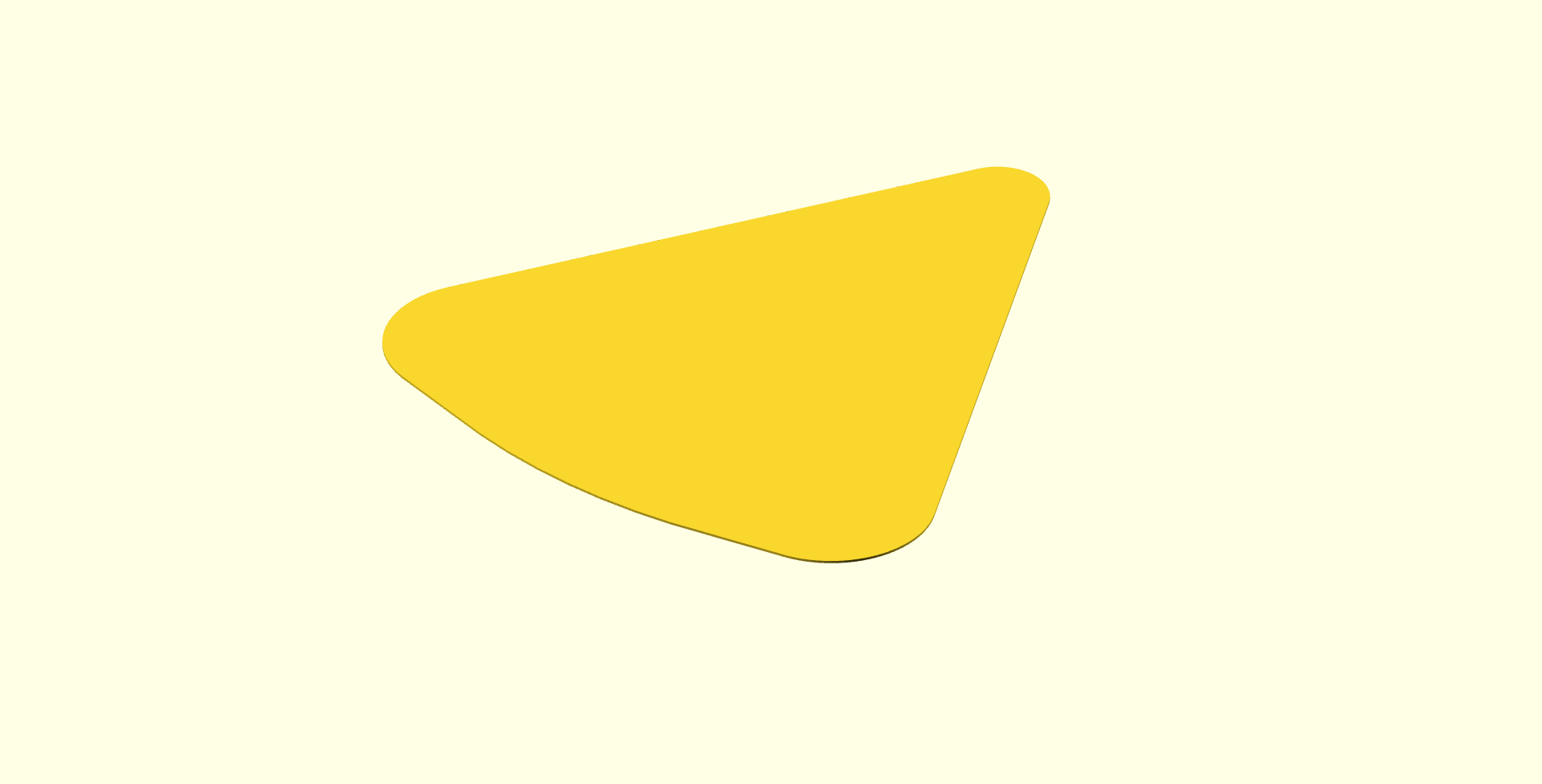
radius = 10; stemHeight = 20; stemBracketHeight = 5; bodyHeight = 20; elongation = 5;
Summary
The faceted vase is an #openscad experiment by @mynameisceline to explore parametric polygonal decor.
Narrative
I chose to create something beautiful and useful. Vases have quite a bit of variety in form and structure and utility—the ongoing issue in my family every Mother’s Day is that my sister and I buy flowers that are too tall for a short vase, too short for a tall vase, too many for a slim vase, or too few for a wide vase. Clearly, the answer is parametric forms.
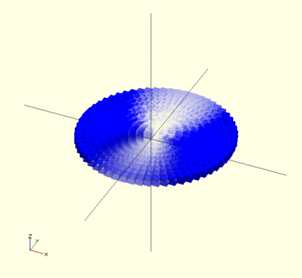
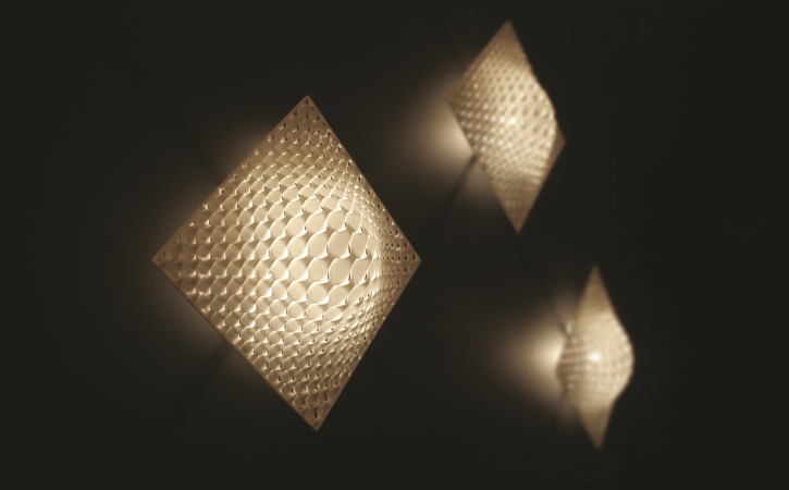
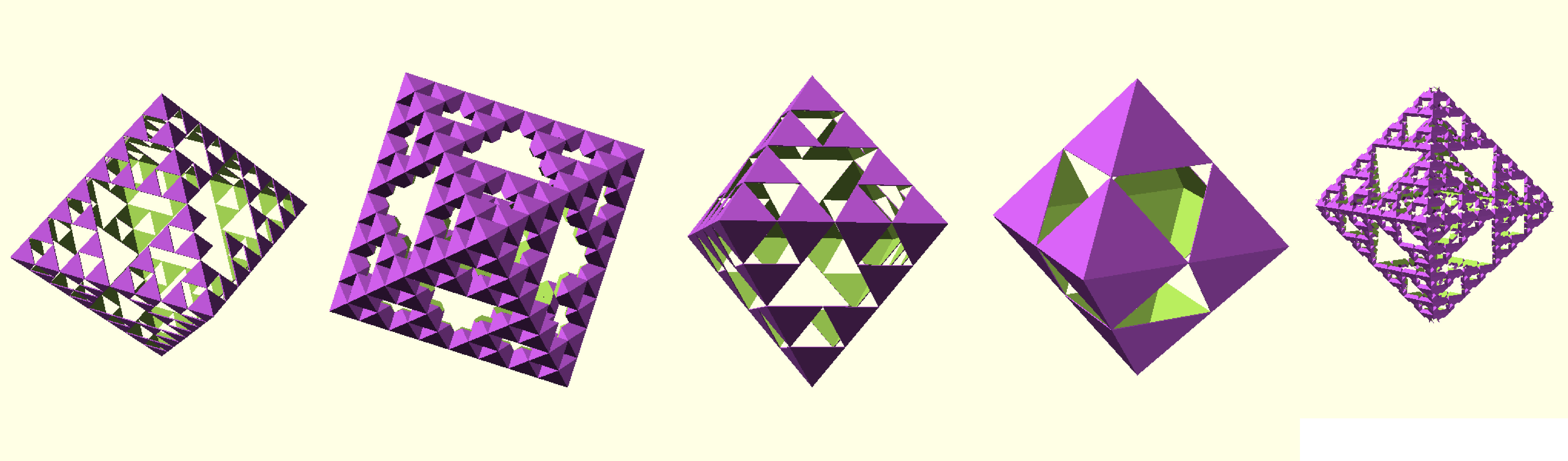
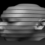
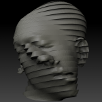
I’m also a huge fan of polygonal shapes (2D and 3D) in art and design. It so happens I have a pinboard full of polygonal inspiration:
Follow Celine Nguyen’s board Polygonal Geometries on Pinterest.
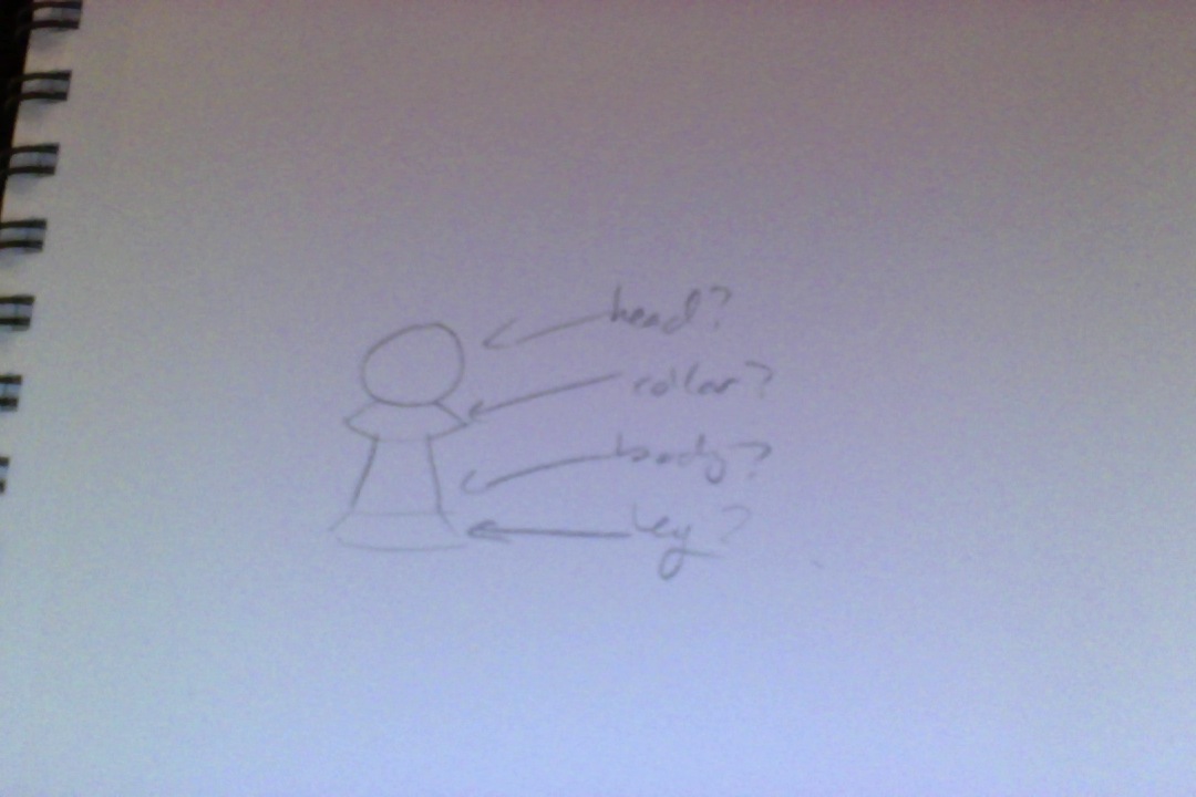
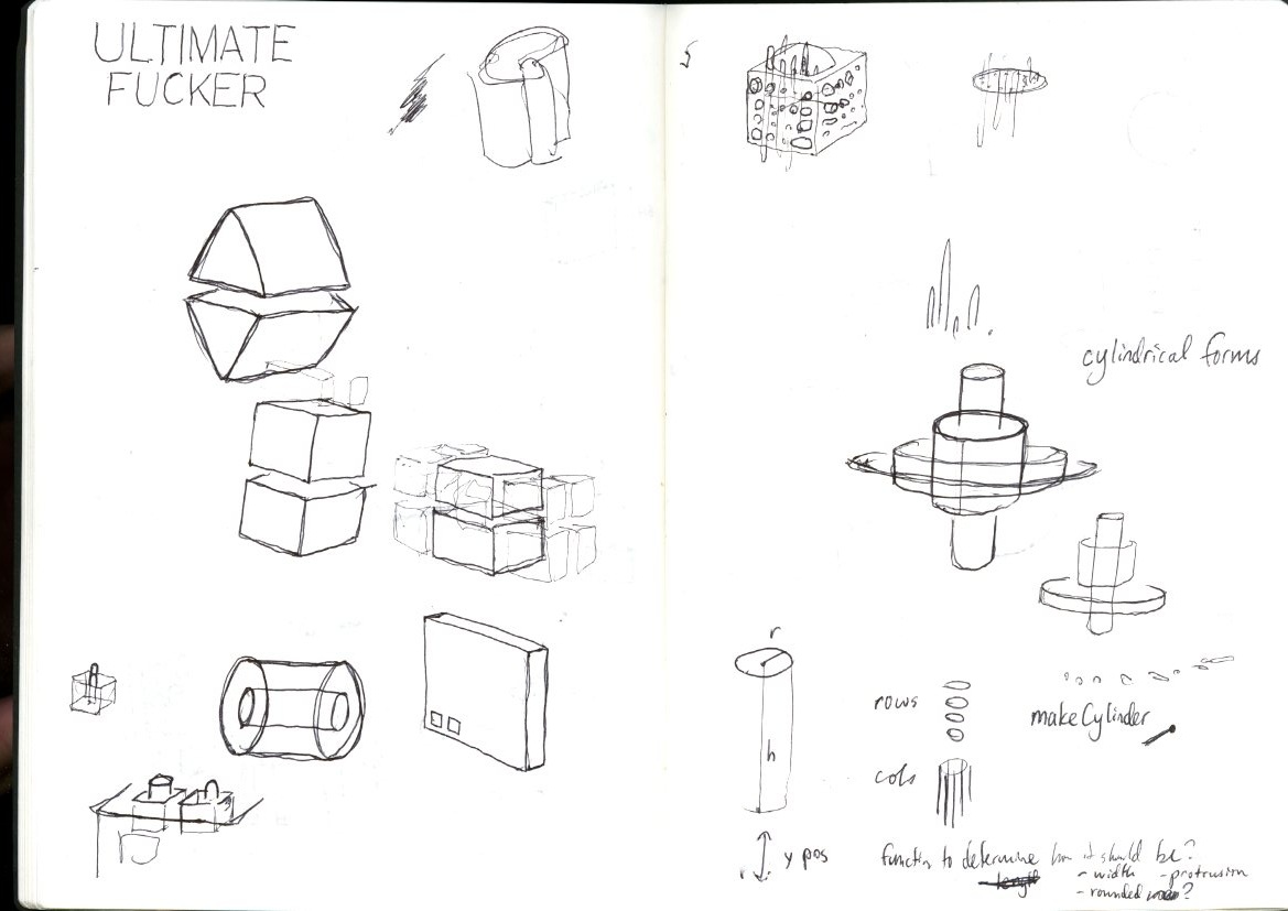
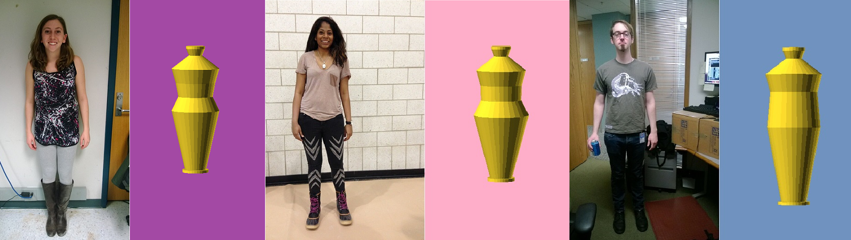
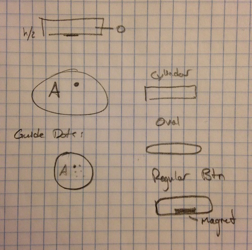
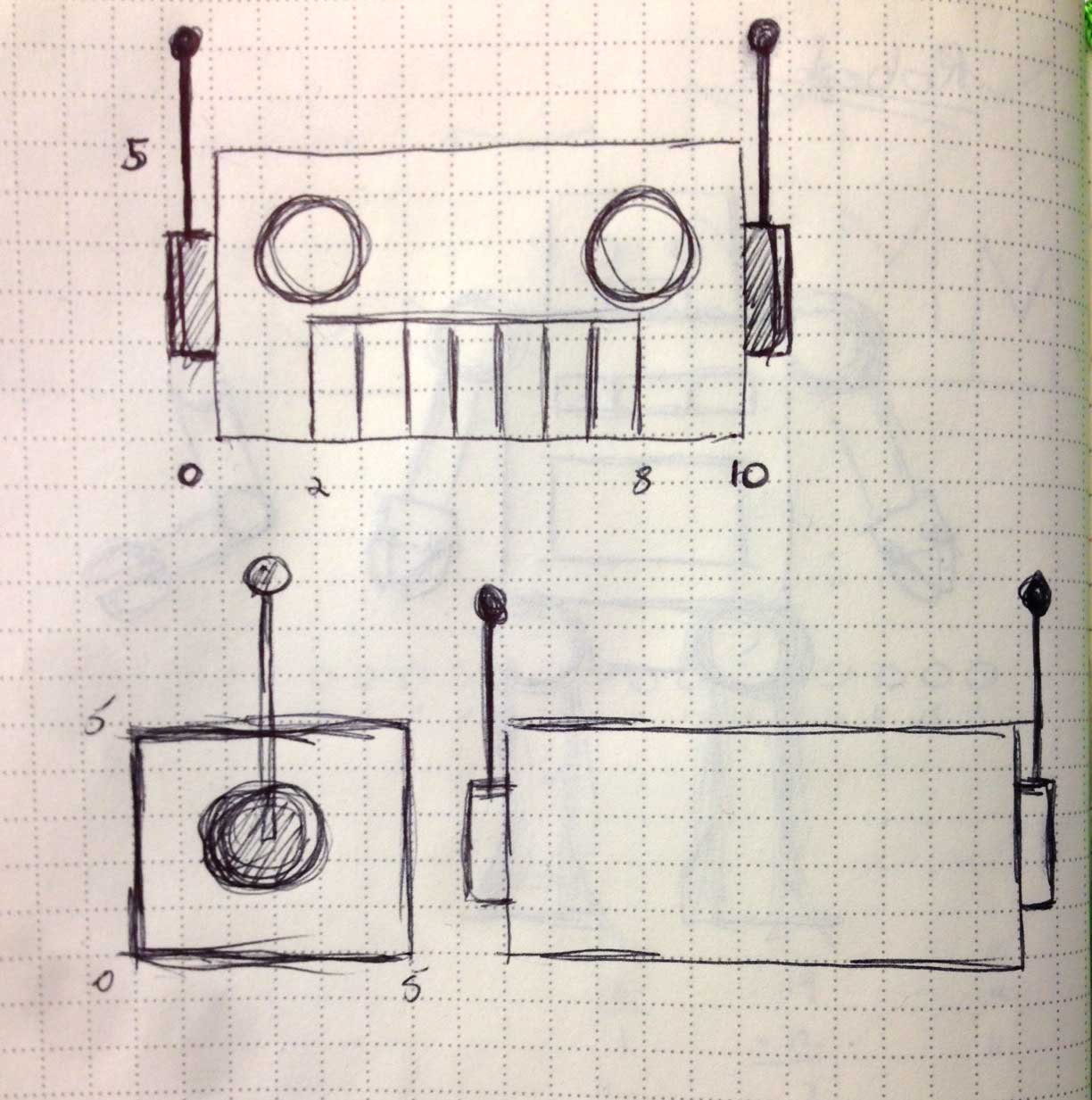
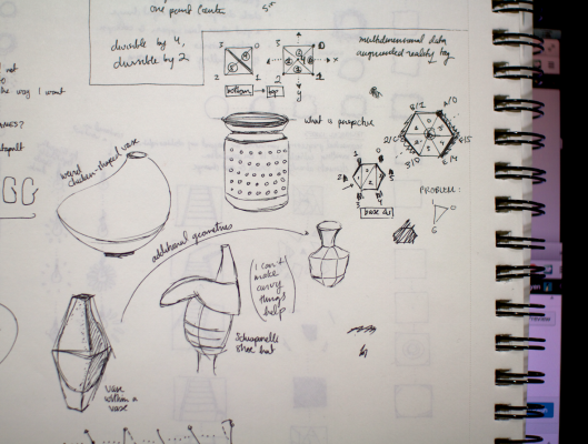
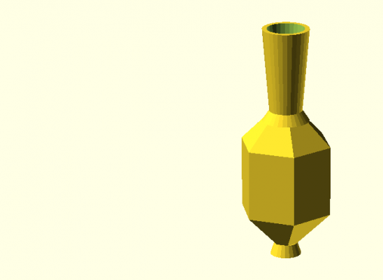
So. I made two initial sketches of polygonal vases (one with a faceted body and smoother stem, one with a faceted body and a curved inner cavity), but went with the first option to give me more customization/parameterization options. I’m pretty happy with how it turned out, since it’s reasonably changeable and I enjoy the different character that a tall/elegant vase and a small/squat vase convey.
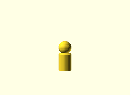
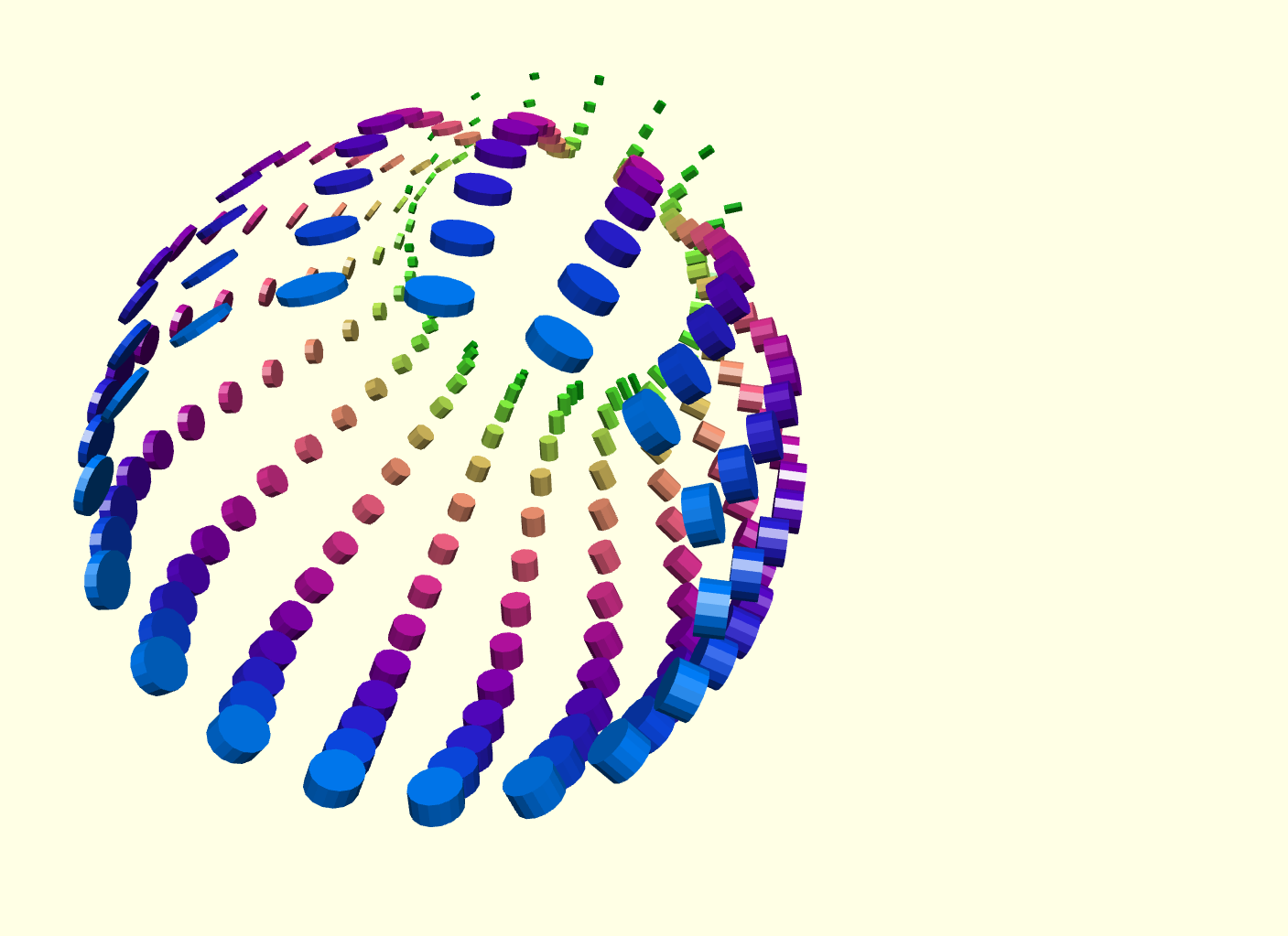
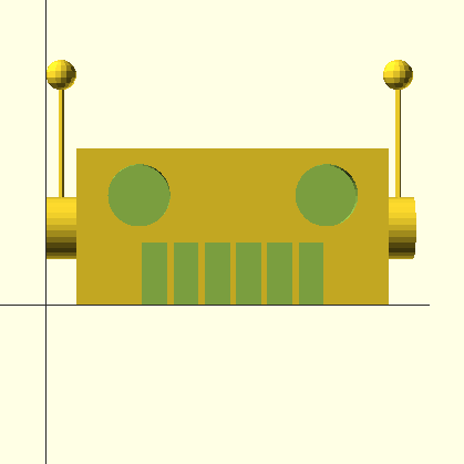
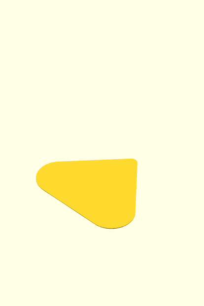
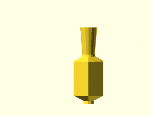
radius = 20; stemHeight = 20; stemBracketHeight = 2; bodyHeight = 20; elongation = 10;
My initial sketch & vision for this called for the stem of the vase to be smoothly tapered and curved along the side (kind of like a conventional vase) to get a good contrast between the chunky/blocky part of the vase and a smoother, more delicate bit. I unfortunately couldn’t figure this out (although I spent some enjoyable time playing around with minkowski() and hull() in the attempt).
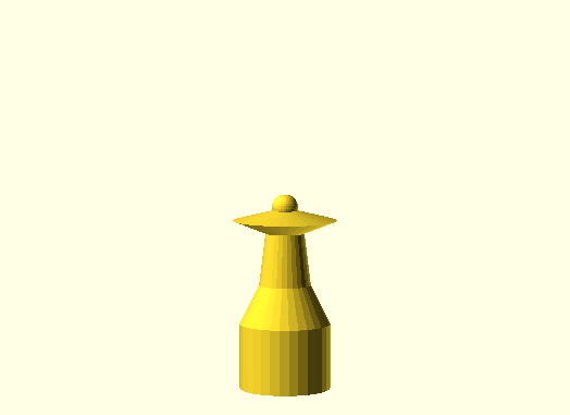
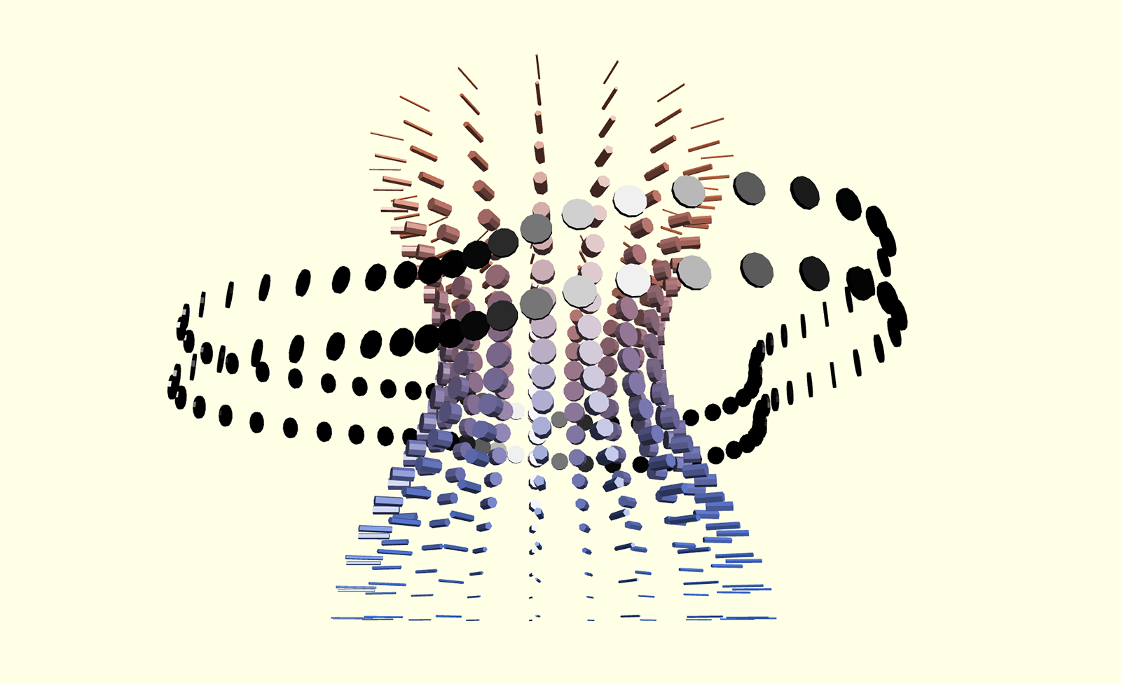
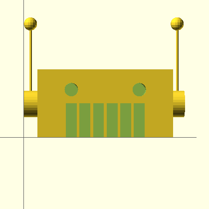
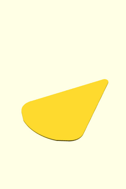
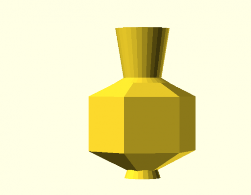
radius = 20; stemHeight = 40; stemBracketHeight = 5; bodyHeight = 30; elongation = 20;
Code
(For some reason Thingiverse won’t finish processing my file uploads ; n ; )
+ Github repo.
// manipulable parameters! radius = 10; // default: 10 stemHeight = 20; // default: 20 stemBracketHeight = 1; // default: 1 bodyHeight = 20; // default: 20 elongation = 5; // default: 8 // parameters i ask you not to touch hollowThickness = 2; opening = 4; stemTopBase = radius / 2; stemBottomBase = radius / 3; // stem translate([0, 0, elongation]){ difference() { cylinder(h = stemHeight, r1 = stemBottomBase, r2 = stemTopBase, center = false); cylinder(h = stemHeight, r1 = stemBottomBase - hollowThickness, r2 = stemTopBase - hollowThickness, center = false); } } // stem bracket translate([0, 0, 0]) { difference() { cylinder(h = elongation + stemBracketHeight, r1 = stemTopBase, r2 = stemBottomBase, center = false); cylinder(h = elongation + stemBracketHeight, r1 = stemTopBase - hollowThickness, r2 = stemBottomBase - hollowThickness, center = false); } } // top translate([0, 0, 0]) { difference() { polyhedron( points = [[radius * 0.87, radius * 0.5, 0], // 0 [radius * 0, radius * 1, 0], // 1 [radius * -0.87, radius * 0.5, 0], // 2 [radius * -0.87, radius * -0.5, 0], // 3 [radius * 0, radius * -1, 0], // 4 [radius * 0.87, radius * -0.5, 0], // 5 [0, 0, elongation]], // the apex point, 6 triangles = [[0, 6, 1], [1, 6, 2], [2, 6, 3], [3, 6, 4], [4, 6, 5], [5, 6, 0], // sides [0, 1, 3], [1, 2, 3], [0, 3, 4], [0, 4, 5]] // base ); cylinder(h = elongation, r1 = stemBottomBase - hollowThickness, r2 = stemTopBase - hollowThickness, center = false); } } // body translate([0, 0, -bodyHeight]) { difference() { linear_extrude(height = bodyHeight, center = false, convexity = 10) { polygon( points = [[radius * 0.87, radius * 0.5], // 0 [radius * 0, radius * 1], // 1 [radius * -0.87, radius * 0.5], // 2 [radius * -0.87, radius * -0.5], // 3 [radius * 0, radius * -1], // 4 [radius * 0.87, radius * -0.5]] ); } cylinder(h = bodyHeight, r1 = stemTopBase - hollowThickness, r2 = stemTopBase - hollowThickness, center = false); } } // bottom translate([0, 0, -bodyHeight]) { rotate(a = [0, 180, 0]) { polyhedron( points = [[radius * 0.87, radius * 0.5, 0], // 0 [radius * 0, radius * 1, 0], // 1 [radius * -0.87, radius * 0.5, 0], // 2 [radius * -0.87, radius * -0.5, 0], // 3 [radius * 0, radius * -1, 0], // 4 [radius * 0.87, radius * -0.5, 0], // 5 [0, 0, elongation]], // the apex point, 6 triangles = [[0, 6, 1], [1, 6, 2], [2, 6, 3], [3, 6, 4], [4, 6, 5], [5, 6, 0], // sides [0, 1, 3], [1, 2, 3], [0, 3, 4], [0, 4, 5]] // base ); } } // base translate([0, 0, -bodyHeight - elongation]){ cylinder(h = 5, r1 = radius / 3, r2 = radius / 4, center = false); } |