Dorsek – DrawingSoftware

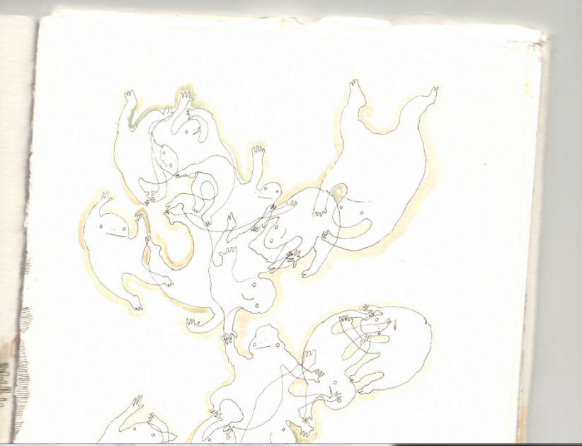
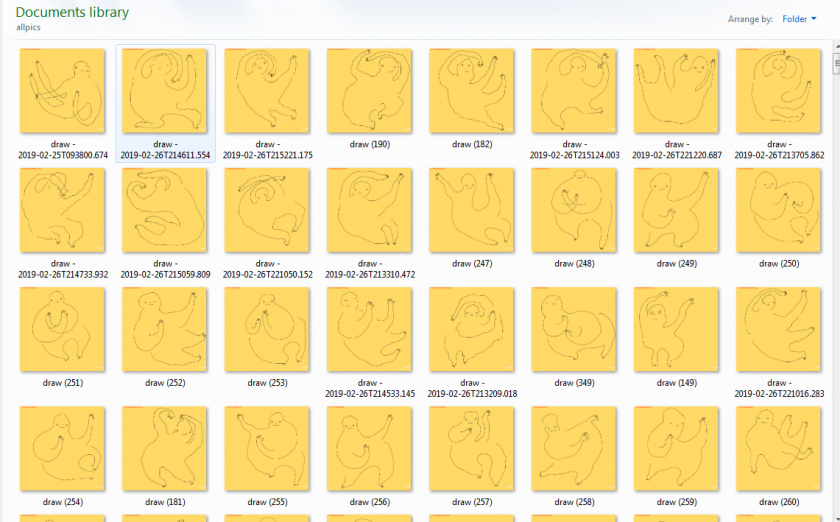
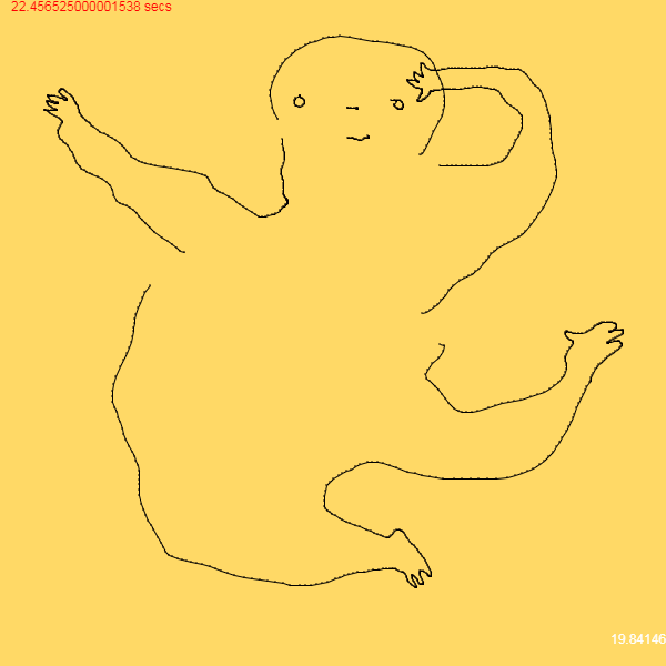
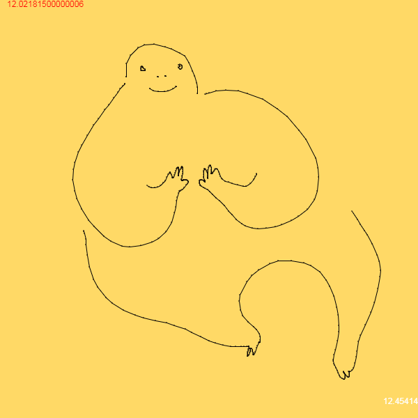
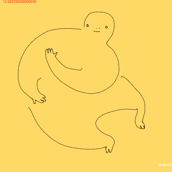
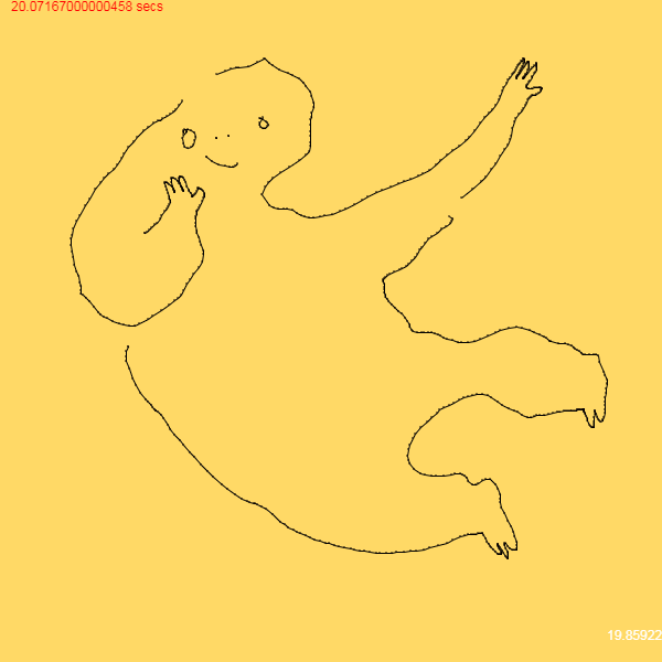
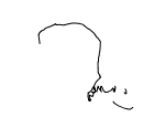
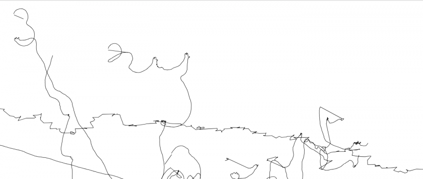
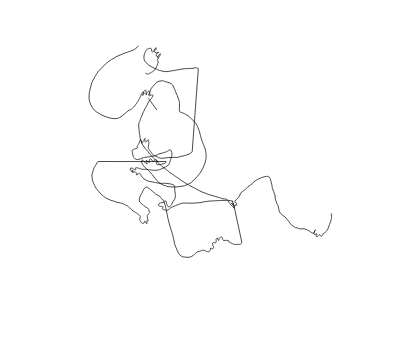
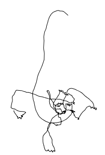
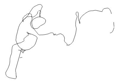
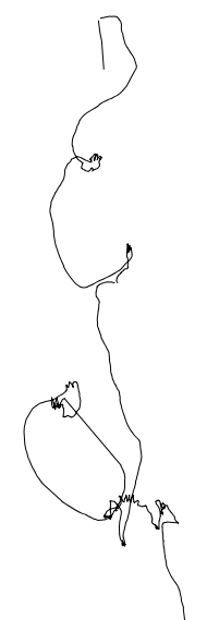
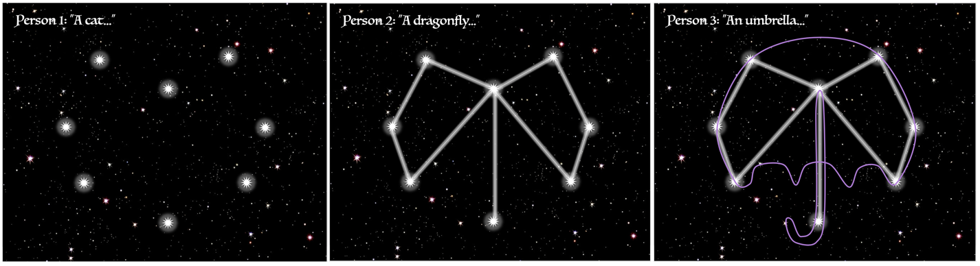
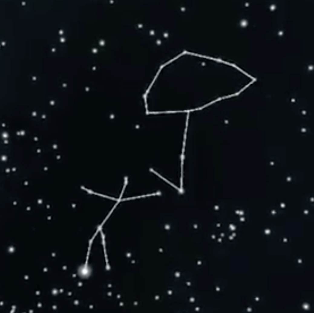
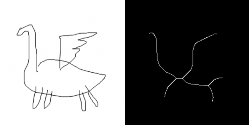
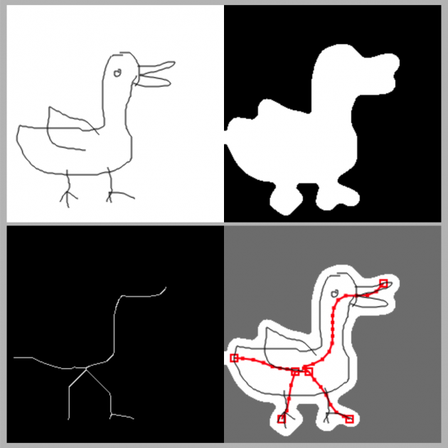
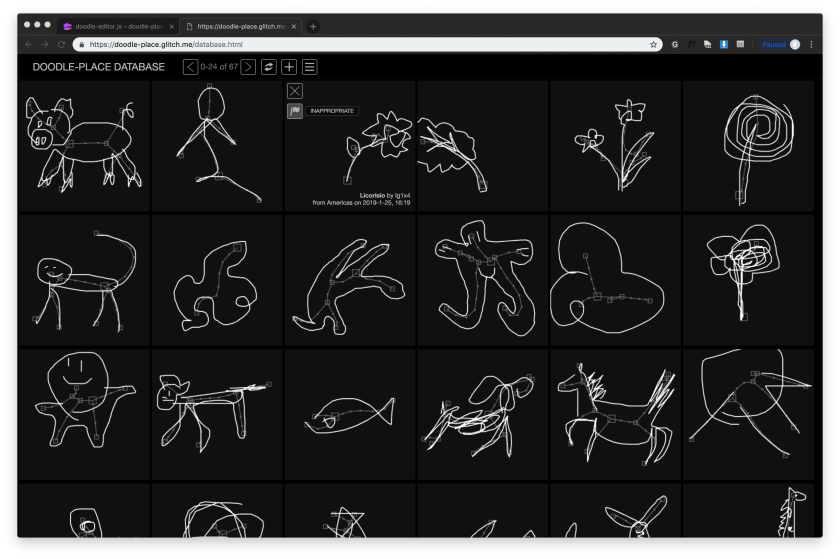
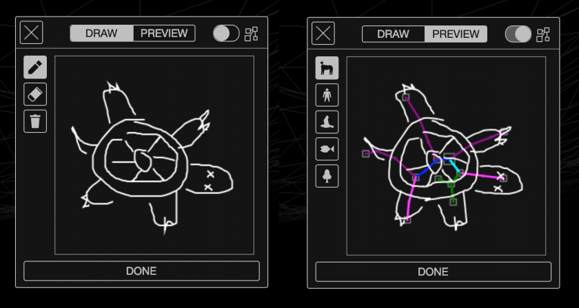
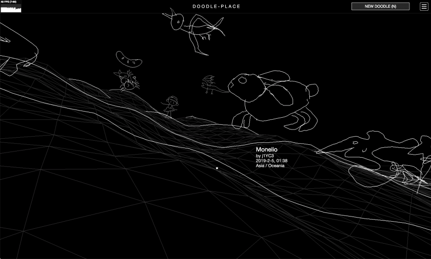
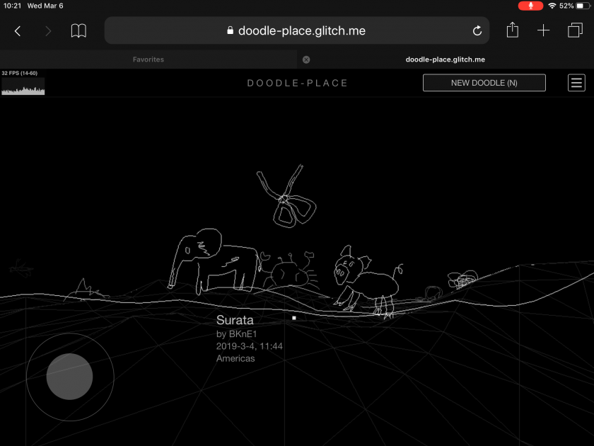
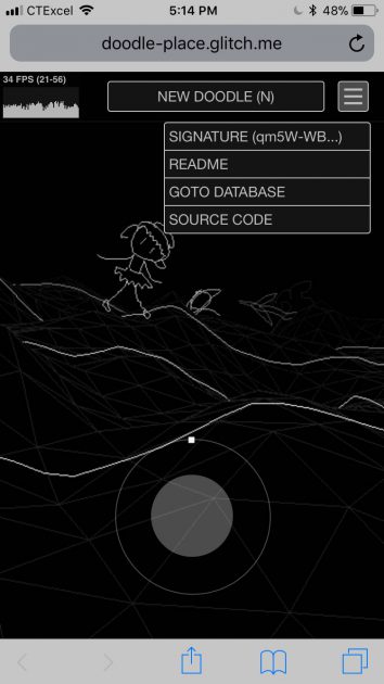
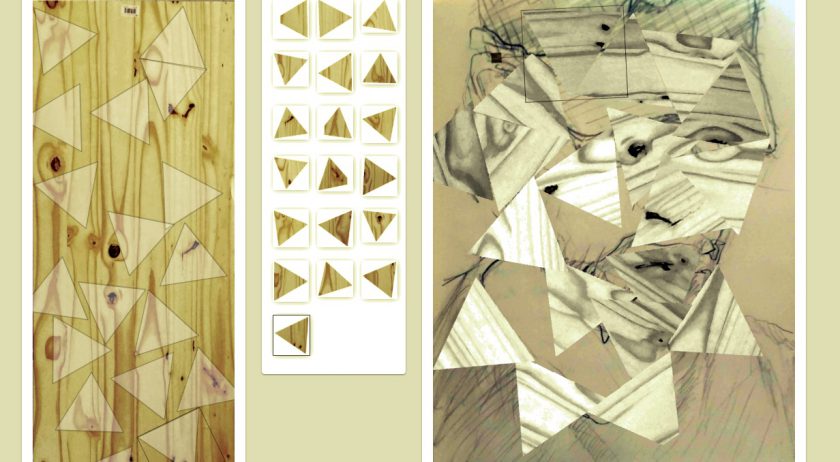
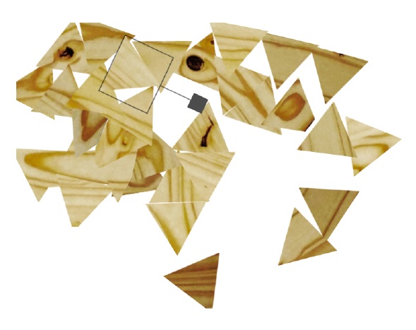
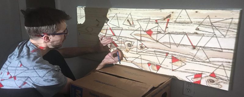
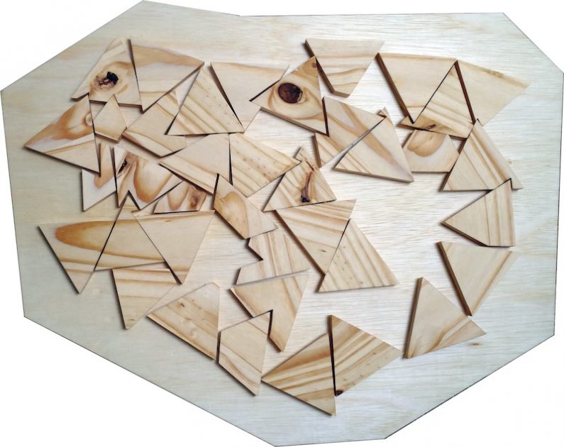
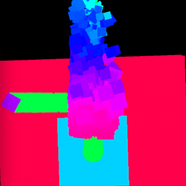
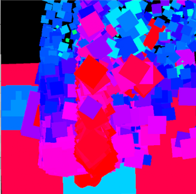
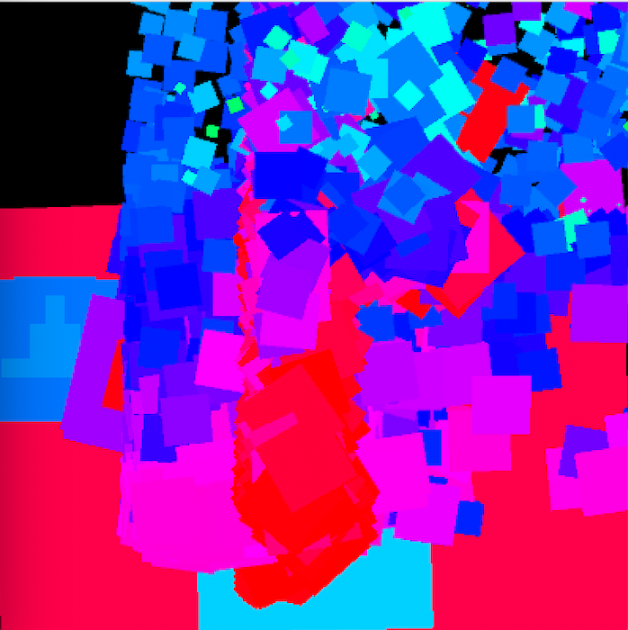
Some screenshots of the “drawings” after 20 minutes of napping post-video and after implementing a 3rd ‘trigger’/training session

Brain User Interface based Drawing

When stripped down to the bare bones, this project was my first attempt at trying to create a drawing based brain user interface (BUI) using a commercially available brain wave sensing headband (Muse2) in order to do so.

My interest in creating such a piece originally laid in the desire to develop a program that could transcribe your dreams as illustrations while you were unconscious, allowing you to wake up to a image that was supposed to be a transcribed dream journal of sorts… Specifically I wanted to use brainwaves of a sleeping user in order to begin to draw a thing which then would be completed by SketchRNN (when it decided that it was certain it knew what was being rendered), and then move onto the next start of a drawing, repeating over and over until the user wakes up in the morning only to see a composition of “their dream” (or rather what the program believe their dream to be). Unfortunately, this was not achievable in the time given for this project due to a few factors:

a.) The fact that the brain sensing headband didn’t arrive until about 6 days before the project was due

b.) my own unfamiliarity with the programs necessary to make a program like that become reality

Considering the first obstacle in particular I found it conducive to try and narrow down my scope as much as possible to this: a program with which you could use the raw EEG data of your brainwaves to paint with, so essentially using your focus on particular thoughts in order to manipulate a digital painting tool – Though as you will see, this too was much more difficult than I initially expected.

Capturing the drawing of a gnarly yawn
A “close-up” look at how the brush is moving where I focus on the concept of chocolate covered bananas(low position/red) as opposed to the sky (high position/blue)…


Process

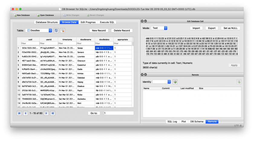
Much like Golan warned me, the “plumbing” for this project seemed to suck up the most amount of time – as it was a great deal of work trying to get information out of the headband in the form of OSC data (so that I could forward it into Wekinator, use machine learning in order to “train” the drawing program, and then from there implement it in processing).
The plumbing actually required a few extra steps, one of the most important being getting to know OSCulator (an extremely valuable tool recommended to me for use by Golan) – even though I had the ability to export the OSC data of the headset via the 3rd party app, museMonitor, all of the OSC data being exported was in the form of several separate messages (a format that Wekinator didn’t seem to recognize) so I used OSCulator in order to format the OSCdata into Wekinator’s standardly and only accepted float list format. Though there is a great deal of information on muse headset data, and wekinator alone – there is hardly any information on the use of wekinator, OSCulator, and muse in combination so much of my time was spent doing research simply on how to get the information from one platform to another.

Overall, this slightly frustrating and certainly trying process took me the better half of 5 days, and as a result I wasn’t able to spend as much time on the concept or actual training of the application unfortunately. In retrospect, I’m glad I was able to accomplish as much as I did considering how little information I felt there was regarding such a niche method in addition to how little I initially felt I could comprehend. It was definitely an amazing learning experience.

Future Iteration…

So, even though I do have a BUI that functions somewhat coherently, I do think that I would have liked to spend more time on fleshing out my original concept or even implementing features to turn this into a clever game (such as a very difficult game of “snake” or some sort of a response to fugpaint that takes frustration with interface to a whole new level provided nearly impossible workarounds). I will be spending more time on this because it’s been a pretty engaging  idea to play with/develop.


Special thanks to:

Golan (for introducing me to some very helpful tutorials on how to use Wekinator, for turning me onto OSCulator which I eventually used to get the OSC data into Wekinator, and for encouraging me to pursue the development of this project!)

Tatyana (for suggesting Wekinator to me when I initially pitched my idea to her before we shared our research in class for the midway point)

Grey (for making some very helpful suggestions as to how I could get the OSC data into Wekinator without the use of OSCulator, and for offering his assistance to me )

Tom (for acquiring the muse headband!)


takos-DrawingSoftware

My goal was to train a model to draw like I do (see sketchbook except below)


Input:  I drew 1200 friends:


I wrote a quick p5 sketch that stores the data in 3stroke format, which keeps track of the difference in x & y of each point , and weather or not a specific point is the first point in a stroke or not.


I used SketchRNN, and trained my own model off of the drawings I did. This was the first result I got as output, and so far the only one with a distinguishable face


Other models as I’ve adjusted variables in the output:


jaqaur – DrawingSoftware

ASTRAEA

A Constellation Drawing Tool for VR

Astraea is a virtual reality app for Daydream in which the user can draw lines to connect stars, designing their own constellations. It was named after the figure in Greek mythology Astraea, who is daughter of Astraeus and Eos (gods of dusk and dawn, respectively). Her name means “starry night” and she is depicted in the constellation Virgo.

The app puts the user in the position of stargazer, in the middle of a wide open clearing on a clear night. They draw using a green stargazing laser, and can also use the controller to rotate the stars to their desired position. All stars’s magnitude and position came from the HYG database, and hovering over a star displays its name (if the database has it).

Since constellations– and the stars in general–are so connected to myths, legends, and stories, I imagine Astraea as an invitation for people to tell their own stories. By drawing their characters and symbols in the sky, users give them a place of importance, and can identify them in the real sky later. At the very least, it’s a fun, relaxing experience.

Design Process

About half of the work time for this project was spent just coming up with the idea. I was originally going to make something using GPS and tracking multiple people, but later decided that the networking involved would be too difficult. Then I thought about ways to constrain what the user was able to draw, but in a fun way. My sisters and I like to play a game where one of us draws a pseudorandom bunch of 5-10 dots, and another has to connect them and add details to make a decent picture (though I’m sure we didn’t invent this, I don’t know where it came from. It reminds me a bit of “Retsch’s Outlines” that Jonah Warren mentioned in “The Act of Drawing in Games”).

Shortly after that, I landed on constellations. I thought about how (at least in my experience), many constellations barely resemble the thing they were supposed to be. Even with the lines in place, Ursa Major looks more like a horse than a bear to me… This made me think that constellation creation and interpretation could be a fun game, kind of like telephone. I made the following concept art for our first check-in, depicting a three-step process where someone would place stars, someone else would connect them, and a third person would interpret the final picture. This put the first person in the position of a Greek god, placing stars in the sky to symbolize something, and the other people in the position of the ancient Greeks themselves, interpreting (and hopefully comedically misinterpreting) their god’s message.

Though this was a kind of fun concept, it was definitely missing something, and my discussion group helped clarify the idea a great deal. They suggested using the positions of real stars, and putting it in VR. After that, I designed and built Astraea–not as a game but a peaceful drawing experience.

Design Decisions

I don’t have time to discuss every decision I made for this project, but I can talk about a few interesting ones.

Why Daydream?

Google Daydream is a Mobile VR for Android devices, and as such, it is significantly more limited than higher-end hardware like the Oculus Rift or HTC Vive. It has only 3 degrees of freedom, which wasn’t a big problem for the stargazing setting, but its less precise controller makes selecting small stars trickier than would be ideal. The biggest problem that came with using mobile VR is the lower resolution and the chromatic aberration that appears around the edges of one’s vision. This is especially noticeable in Astraea, as the little stars turn into little rainbow balls if you look off to the side.

All of that said, it was still important to me that Astraea was a mobile application rather than a full room-scale VR game. Platforms like Vive and Oculus are not as accessible to people as mobile VR, and I definitely don’t envision this as an installation piece somewhere. Even for people with high-tech headsets in their home, the big controller/HMD/tracker setups for them feel too intense for Astraea. No one uses a Vive while lying in bed, and I want Astraea to be cosy, easy to put on for some stargazing before you go to sleep. So mobile VR worked really well for that. Daydream just happened to be the type of mobile VR that I have, so that’s why I picked it. I’ve been meaning to learn Daydream development, and I finally did it for this project, so that’s a bonus!

Why do the stars look that way?

Way too much time went into designing the stars for Astraea. They went through many iterations, and I actually went outside for some stargazing “research.” I determined that stars (at least the three visible in Pittsburgh) look like small bright points of light, with a softer, bigger, halo of light around them depending on their brightness. Their “twinkle” looks like their halo growing, shrinking, and distorting, but their center point is fairly constant. That’s basically what I implemented. Small spheres for the stars themselves, with sprites that look like glowing circles around them. The glowing circles change their size randomly, and the stars are sized based on how bright they are from Earth. I did not include all 200,000+ stars in the dataset; instead I filtered out the ones with Magnitude higher than 6 (ie. the very dim ones) so the user wouldn’t have to deal with tiny stars getting in the way. This left me with about 8,000 stars, which works pretty well.

Why does everything else look that way?

The ground is there just to block out the stars below you. The treeline is to give it a hint of realism. But really, they are both supposed to be very simple. I want your attention directed upwards. The laser is green because that’s the actual color laser that stargazers use. My friend told me this when I was lamenting how I didn’t know what to make the laser look like. It turns out that green and blue are the only colors that are powerful enough for this sort of thing, and green is used in practice like 90% of the time. I thought that was a neat fact, so I included it in the game. I chose to have no moon because it would block stars, get in the way, and be distracting. So you can pretend it’s a new moon. However, I might put a moon back in later (or a moon on/off option), in case some people want to incorporate it into their drawings.

“Man Losing Umbrella”

Other Thoughts

I am very proud of Astraea. I genuinely enjoy using it, and I learned a lot about mobile VR development in the creation of it. There are a few more features I want to add and touch-ups I want to make, but I intend to make this app publicly available in the future, and hopefully multi-user so people can draw for each other in real time as they share their stories.

yeen-DrawingSoftware

My original goal is to create a visual generator that uses a keyboard interface as the only input and uses the advantage of MIDI sequencer to sequence visuals. I started by exploring Jitter in Max/MSP, and ended up creating 2 projects that are not quite close to my goal.

The first project “keyboard oscilloscope” captures my effort to associate MIDI input with simple geometric shapes. Each additional note input increases the number of cubes that form the shape of a ring, whose overall x position is associated with a low-frequency-oscillator on an oscillator and y position with another low-frequency-oscillator on a low-pass filter.  What I found interesting about this oscilloscope is, as we can see and hear in the video, as the modulation rate increases, we start to hear the beating effect and the changing visuals align with the frame rate and become “static”. Since I started this project by algorithmically generate everything, the color, positions of cubes, number of cubes, it became challenging to proceed to implement the sequencer functionality.

However, I really wanted to build a visual machine that can potentially become a visual sequencer. So I created “weird reality”, which is a virtual space that contains 64 spheres floating around, each corresponds to a different sin wave. “weird reality” has 3 modes:

1. Manual: manually dragging the spheres around and hear the raising and falling of sin waves; 2. turning on the demon mode and the spheres will automatically go up and down; 3. turning on the

2. Demon mode: the spheres automatically go up and down; 3. turning on the

3. Weird mode: the world has an invisible force field that can only be traced by spheres that move around it. The world sometimes changes its perspective and rotates around, and that’s when the force field is traced by all spheres.

ngdon-DrawingSoftware

doodle-place

Check it out at https://doodle-place.glitch.me

doodle-place is an online world inhabited by user-submitted, computationally-animated doodles. You can wander around and view doodles created by users around the globe, or contribute your own.

Process

To make this project, I first made a software that automatically rigs and animates any doodle made by users. It does so using some computer vision. Then I wrote server-side and client-side software to make the world and the database behind it running. The process is explained below.

doodle-rig

Skeletonization

To rig/animate a doodle, I first need to guess the skeleton of it. Luckily, there’s something called “skeletonization” that does just that. Thanks to Kyle McDonald for telling me about it one day.

The idea of skeletonization is to make the foreground thinner and thinner until it’s 1px thick.

At first I found a OpenCV implementation, but it was quite bad because the lines are broken at places. Then I found a good implementation in C++. I ported it to javascript. However it runs very slow in the browser, because it iterates through every pixel in the image multiple times and modifies them. However, I discovered gpu.js, which can compile kernels written using a subset of javascript into WebGL shaders. So I rewrote the skeletonization algorithm with gpu.js

The source code and demo can be found at:

https://skeletonization-js.glitch.me

You can also import it as a javascript library to use in whatever js project, which is what I’m doing for this project.

Inferring rigs

Since the skeletonization is a raster operation, there is still the problem on how to make sense of the result. We humans can obviously see the skeleton meant by a resultant image, but for computers to understand I wrote something that extracts it.

The basic idea is that I scan the whole image with a 8×8 window for non-empty patches, and I mark the first one I found as root.

I check all 4 edges of the root patch, and see which of the 8 directions have outgoing lines. I’ll follow these lines and mark the patches they point to as children. Then I do this recursively to extract the whole tree.

Afterwards, an aggressive median-blur filter is applied to remove all the noise.

The source code and demo can be found at:

https://doodle-rig.glitch.me

Again, this can be used as a library, which is what I did for this project.

Inferring limbs & Animation

I made 5 categories for doodles: mammal-oid, humanoid, bird-oid, fish-oid, and plant-oid. For each of them, I have a heuristic that looks at the shape of skeleton and decide which parts are legs, arms, heads, wings, etc. Though it works reasonably well on most doodles, the method is of course not perfect (because it doesn’t use machine learning). But since the doodle can be anything (the user might submit say a banana as a humanoid, in which case no method will be correct in telling which parts are legs), I embraced the errors as something playful.

Then I deduced separate animation for different limbs.  For example a leg should move rapidly and violently when walking, but a head might just bob around a little bit. I also tried just totally random animation, and I almost liked insane randomness better. I’m still working on the sane version.


Database & Storage

Structure

I use SQLite to store the doodles. This is my first time using SQL. I find learning it interesting. Here is a sqlite sandbox I made to teach myself:

https://ld-sql-lab.glitch.me

Anything you post there will be there forever for everyone to see…

But back to this project, I encode the strokes and structure of each submitted doodle into a string, and insert it as a row along with other meta data:

  • uuid: Generated by the server, universally unique identifier to identify the doodle.
  • userid: The name/signature of a certain user to put on their doodles, doesn’t need to be unique
  • timestamp: time at which the doodle is created, also contains the time zone information, which is used to estimate the continent where the user is on without tracking them.
  • doodlename: The name of the doodle given by user
  • doodledata: strokes and structural data of the doodle.
  • appropriate: whether the doodle contains inappropriate imagery. All doodles are born as appropriate, and I’ll check the database periodically to mark inappropriate ones.

Management

I made a separate page (https://doodle-place.glitch.me/database.html) to view and moderate the database. Regular users can also browse that page and see all doodles aligned in a big table, but they won’t have the password to flag or delete doodles.

Golan warned me that the database is going to be full of penises and swastikas. I decided that instead of deleting them, I’ll keep them but also flag them as inappropriate so they will not spawn. When I’ve collected enough of these inappropriate doodles, I’ll create a separate world so all these condemned doodles can live together in a new home, while the current world will be very appropriate all the time.

Engine

GUI

The default HTML buttons and widgets looks very generic, so I wrote my own “skin” for the GUI using JS and CSS.

Turns out that modern CSS support variables which can be programmatically set with JS. This recent discovery made my life a lot easier.

I created an entire set of SVG icons for the project. I used to use Google’s Material Icon font, but it turns out that what I need this time is too exotic.

Making the doodle editor GUI was more time-consuming than writing actual logic / developing algorithms.

3D

At first I thought I could get away with P5.js 3D rendering. Turns out to be slow as crawl. After switching to three.js, everything is fast. I wonder why, since they both use WebGL.

The lines are all 1px thick because of Chrome/Firefox WebGL implementation doesn’t support line width. I would be happier if they can be 2px so things look more visible, but I thick currently it’s fine. Workaround such as to render lines as “strip of triangles” is way too slow.

Terrain

I’ve generated a lot of terrains in my life so generating this one isn’t particularly hard. But in the future I might give it more care to make it look even better. Currently it is a 2D gaussian function multiplied with a perlin noise. This way the middle part of the terrain will be relatively high, with all the far-away parts having 0 height. The idea is that the terrain is an island surrounded by waters, so the players can’t just wander off the edge of the world.

The plant-oids will have a fixed place on land, the humanoids and mammal-oids will be running around on land, the bird-oids will be flying around everywhere, and the fish will be swimming in the waters around the island.

The terrain is generated by the server as a height map. The height map is a fixed-size array, with the size being its resolution. The y coordinate of anything on top of the terrain is calculated from its x and z coordinates, and non-integer positions are calculated using bilinear-interpolation. This way mesh collision and physics stuff are avoided.

Initially I planned to have the terrain look just like a wireframe mesh. Golan urged me to think more about it, such as outlining the hills instead so the look will be more consistent with doodles. I implemented this by sampling several parallel lines on the height map normal to the camera’s direction. It’s quick, but it sometimes misses out the top of the hills. So I still kept the wireframe as a hint. In the future I might figure out a fast way, perhaps with some modified toon shader to draw exactly the outline.

Control

The user can control the camera’s rotation on y axis. The other two rotations are inferred  by the terrain beneath the user’s feet, with some heuristics. There’s also a ray-caster that acts like a cursor, which determines where new user-created doodles will be placed. The three.js built-in ray caster on meshes is very slow, since I have really really big mesh that is the terrain. However since terrains are not just any mesh and have very special geometric qualities, I wrote my own simple ray caster based on these qualities.

I want the experience to be playable on desktop and mobile devices. So I also made a touch-input gamepad and drag-the-screen-with-finger-to-rotate-camera.

^ On iPad

^ On iPhone

Libraries:

  • three.js
  • OpenCV.js
  • gpu.js
  • node.js
  • sqlite
  • socket.io
  • express

Evaluation

I like the result. However I think there are still bugs to fix and features to add. Currently there are ~70 doodles in the database, which is very few, and I’ll need to see how well my app will perform when there are many more.

Some more doodles in the database, possibly by Golan:

ulbrik-DrawingSoftware

Wood Grain Collage Tool

Production systems are streamlined for homogenous materials. Most technologies ask us to crudely reshape the natural world into the uniform shapes they require (think tractors and factory farms). In contrast, the Wood Grain Collage Maker embraces the irregularity of natural materials.

Screenshot of a collage

The Wood Grain Collage Maker is a web-based tool (built with ReactJS, Fabric.js, and P5.js) for planning a collage using the grain in a piece of wood and a sketch. It allows users to drag, rotate, and scale selections and placements of wood to construct a collage. Once finished, the user can export the cut and layout files to make the collage IRL.

Wood Grain Collage Maker Demo

Process:

The collage maker tool is part of a larger work flow:

Overall work flow from source material to artifact, with some ideas that I scratched for now… AI-powered placement and a CNC router work flow ended up being out of scope.

Step 1: Collect the materials: wood with visible grain and a sketch.

A piece of plywood from the hardware store is not a completely natural product, but its wood grain is a heterogenous material and serves the purposes of this project.
Sketches from a museum.

Step 2: Make a collage with the Wood Grain Collage Maker.

Demo of tool in action
Sketched plan the major parts of the software

Step 3: Make the artifact.

Work flow after collage maker. I projected the cuts on the original piece of wood, cut them out with a jigsaw, and assembled them on a board.
Cut file from collage maker ready for projection onto the original board. The red is the overlap that also needs to be removed. In the future, a SVG file could be generated for a CNC router.
Layout file from collage maker.


Tracing out the cut file on the piece of wood.
The physical artifact arranged according to the layout designed by the test user. It is glued together and wiped down with tung oil to bring out the grain.

Evaluation:

Originally, I planned on making a collage design machine that acted as a thoughtful, “creative” partner. It would suggest new, provocative ideas while the user worked. The tool would help the user quickly navigate and make leaps through the design space. However, before I could do this I needed a digital collage tool in which to integrate the assistant.

The design space as an archipelago of islands and the designer as a small boat. Tools that make a process more convenient help the designer cover more ground and expand the search area for design treasure. But what about great leaps to distant new continents? Could a “creative” machine help with this?

I created the Wood Grain Collage Maker to facilitate the collage work flow, calculate overlaps, and produce the documents necessary for the physical realization of the collages. My hope was that the tool would allow me to be efficient enough to find a state of creative flow.

When tested with a small, captive audience of one, I received positive feedback that using the collage tool was fun and soothing, much like a puzzle.  In addition to the enjoyment of making the design, it was also exciting to put together at the end. As it turned out, the software showed more potential as a form of puzzle than as a tool for production. Maybe adding an intelligent system is unnecessary…


lumar-DrawingMachine

FINAL:

so. I didn’t end up liking any of my iterations or branches well enough to own up to them. I took a pass when my other deadlines came up but I had a lot of fun during this process!

PROCESS

Some sketches —

Some resources —

Potential physical machines…

a google experiments for a projector lamp http://nordprojects.co/lantern/

1st prototype —

^ the above inspired by some MIT Media Lab work, including but not limited to —

Some technical decisions made and remade:

welp. I really liked the self-contained nature of a CV aided projector as my ‘machine’ for drawing so I gathered all 20+ parts —

when your cords are too short.

printed somethings, lost a lot of screws…and decided my first prototype was technically a little jank. I wanted to try and be more robust so I got started looking for better libraries (WEBrtc) and platforms. I ended up flashing the Android Things Operating System (instead of raspbian) onto the Pi. This OS is one that Google has made specially for IoT projects with integration  and control through a mobile android—

and then along the way I found a company that has already executed on the projection table lamp for productivity purposes —

LAMPIX — TABLE TOP AUGMENTED REALITY

they have a much better hardware setup than I do

^ turning point:

I had to really stop and think about what I hoped to achieve with this project because somewhere out in the world there was already a more robust system/product being produced. The idea wasn’t particularly novel even if I believed I could make some really good micro interactions and UX flows, so I wasn’t contributing to a collective imagination either. So what was left? The performance? But then I’d be relying on the artist’s drawing skills to provide merit to the performance, not my actual piece.

60 lumens from Marisa Lu on Vimeo.


…ok so it was back to the drawing board.

Some lessons learned:

  • Worry about the hardware after the software interactions are MVP, UNLESS! Unless the hardware is specially made for a particular software purpose (i.e. PiXY Cam with firmware and optimized HSB detection on device)

ex:  So. 60 Lumens didn’t mean anything to me before purchasing all the parts for this project, but I learned that the big boy projector used in the Miller for exhibitions is 1500+ lumens. My tiny laser projector does very poorly in the optimal OpenCV lighting settings, so I might have misspent a lot of effort trying to make everything a cohesive self-contained machine…haha.

ex: PixyCam is hardware optimized for HSB object detection!

HSB colored object detection from Marisa Lu on Vimeo.


  • Some other library explorations

ex: So back to the fan brush idea testing some HSB detection and getting around to implementing a threshold based region growing algorithm for getting the exact shape…


  • Some romancing with math and geometry again

Gray showed me some of his research papers from his undergrad! Wow, such inspiration! I was bouncing out ideas for the body as a harmonographer  or cycloid machine, and he suggested prototyping formulaic mutations, parameters, and animation in GeoGebra and life has been gucci ever since.