Kinect Portal – Independent Study
Background
Following on my final project from IACD Spring ’11, Kinect Portal, I wanted to pursue an Independent Study to advance several aspects of the interaction. Written in C++ using OpenFrameworks, Kinect Portal was a project that used an opaque acrylic panel in conjunction with an XBox Kinect and a projector.
The first version had significant problems, chiefly the jittery-nature of the displayed image. The rectangle-fitting algorithm I had developed was rudimentary and had a lot of trouble fitting the user’s acrylic panel.
Following on the work from the Spring, my two primary goals for the independent study were to:
- Decrease the jitter of the rectangle significantly.
- Utilize the z-depth given from the Kinect with the image or video.
Outline
There were several key points I had to overcome in order to make this happen. They will be covered in detail in this post, in the following order:
- Setting up a proper developer test console
- Enabling video record / replay with a Kinect for faster development time
- Finding the panel with a depth histogram and OpenCV Thresholding
- Resampling and smoothing the rectangle’s contour
- Capturing the corners of the rectangle
- Re-projecting the image
1. Setting up a proper developer test console
I was amazed to realize how important it was to output the workings of the algorithm visually. It allowed me to see many problems that are too difficult to see with the console or while debugging. Even the resolution was important, and I had to zoom in sections of the contour just to see what was happening. Also, it is really important to have a hotkey to pull up the developer console, or hide it and let the display take over.
I decided to use a combination of Dan Wilcox’s ofxAppUtils and Theo’s ofxControlPanel to build the test harness. ofxAppUtils gave me a few things out of the box, such as a quad-warper and a nice overlay interface for developer controls. Ultimately, I had MANY versions of the test harness.

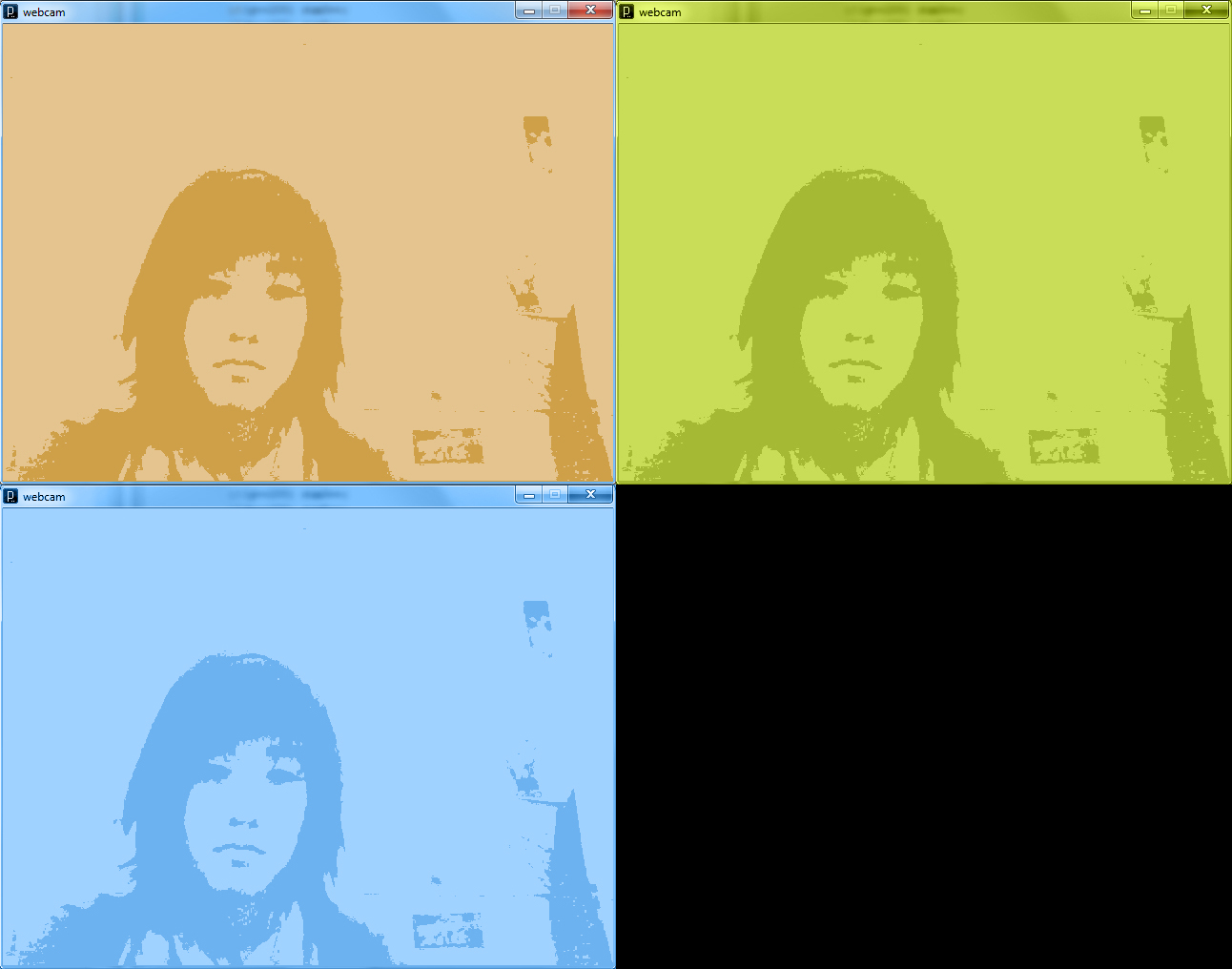
An early version of the Kinect Portal Developer Console showing the contour, depth image, thresholded image and a depth histogram.
This version did not use ofxAppUtils, so I did not actually have a hotkey “overlay” for the console. This was problematic when it was time to use the full display, I had no way to hide the console. After implementing ofxAppUtils, I had a nice “d” hotkey to hide the console.

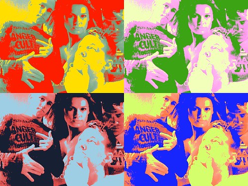
New dev console, including the depth image, depth histogram, variable controls and more information on the corner finding.
The current version of the developer console is much more robust, including controls for adjusting the smoothing, resampling and corner-finding algorithms. There are some difficulties passing the instance of the app down to worker classes, but you can see how I did it in my source. ofxControlPanel provides a nice way to make custom drawing classes, so you can have advanced small displays (as seen in the screenshot above).
2. Enabling video record / replay with a Kinect for faster development time
When working with a Kinect, your test cycle is drastically increased because you have to often stand-up in front of the depth camera! This gets even longer if you need skeletal interaction (ofxOpenNI), which this project didn’t use. ofxKinect includes a Player class that can be used to record and playback data. The files become quite large, but they work very well for holding Kinect RGB and depth data. I implemented a pause and next-frame function that allowed me to hold on a current frame and advance one-by-one in order to test specific pieces of data. I also organized it to switch between live and recorded data with ease.
3. Finding the panel with a depth histogram and OpenCV Thresholding
In order to work with the rectangle, we decided to find it with the Kinect depth camera and use OpenCV to get a contour of it. To find the rectangle, we took the assumption that it would be held out in-front of the user and be the closest item to the camera. This would create a “blob” of depth close to the camera. By taking a histogram of the depth values from the Kinect camera, we were able to isolate the first “blob”: the panel.

Depth Histogram with red dot highlighting the back of the panel.
However, the data coming from the Kinect is quite noisy, with a lot of mini-peaks and valleys. To account for this, I ran a smoothing algorithm that would do nearest-neighbor smoothing – averaging values with it’s two neighbors. About 10 passes over the data did the trick. One key to remember when smoothing is to use two arrays, so you “dirty” one at a time and copy it back over. If you copy as you go, your data will become skewed. Once the histogram is smoothed, all I had to look for was the first trough where the depth’s two neighbors were higher.
4. Resampling and smoothing the rectangle’s contour
Originally, we attempted to detect the corners of the edges by measuring the angles between all of the points along the contour. We later threw this method out, but we performed some critical preparation for this that we decided to keep. This was the resampling and smoothing of the contour.
In order to measure the angle between three points, they must be equally spaced apart. We needed to resample the contour points and make them be evenly spaced. Golan provided me with a method of code to resample the points and space them evenly across the contour. Here are two looks at the contour before and after the resampling:

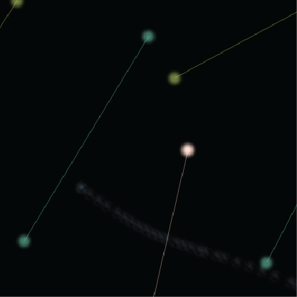
A corner of the rectangle after a resample to 100 points.

The same corner at 400 points resample.
As the user gets further away from the Kinect, the pixel resolution of the depth camera becomes larger (approximately 2cm at 5 feet). This generates a lot of noise in the edges of objects. To mitigate this, we decided to also smooth the contour. This was also possible after a resample, and led to a more stable edge for the rectangle.
5. Capturing the corners of the rectangle
Once the contour was resampled and smoothed, it was time to identify the corners, so we could work with the output display as a rectangle. I spent some time trying to calculate the dot product and angle between the points to isolate the areas of highest curvature. That proved difficult to get working, and when it did it was difficult to determine which were actually corners. Also, because the rectangle could be rotated, and thereby rotated on the screen, it made comparing angle values exceedingly difficult. After much messing around with this, we went to another method.
The other method was to use OpenCV to locate the centroid of the blob, then find the furthest points away from it. All I did was check the hypoteneuse of each point away form the centroid, then select the farthest one. Then I repeated it, but making sure not to select a point within 70 points of that point. I chose 70 after messing with a range of value in the Dev Console, seen below in the blue circles. This number would have to be lowered for a smaller acrylic panel.

Dev Console view with blue circles denoting the barrier around the known corners.
After locating the corners, I noticed that there was still a lot of ‘jitter’ in their positions. This was due to noise from the Kinect, even after the resampling and smoothing. In order to calm this down, Golan suggested we try to use liner regression lines on each side of the rectangle, and choose the corners where they intersected. To do that, I took a section along each edge, but leaving a buffer away from each corner. That way the regressions lines would be based along the length of the side, and not any curvature from the corner.

Notice the yellow Regression Lines along the edges rectangle blob. Their intersections are treated as the true corners.
6. Re-projecting the image
Special Thanks
- Golan Levin for his help, support, incredible problem-solving ability and guidance
- Dan Wilcox
- STUDIO for Creative Inquiry for inviting me to hang out and work!
- Theo and the OF community
External Libraries Used
- ofxAppUtils application harness
- Paul Bourke, Damian Coventry for 2D line intersection
- Roxulu, and Dan Wilcox ofxKinect
- ofxControlPanel
- Lucian Bentea via CodeCogs for the regression analysis algorithm


 +
+ 


