Circuit 9 from Outer Space: Photoresistor Documentation
Building things is fun!
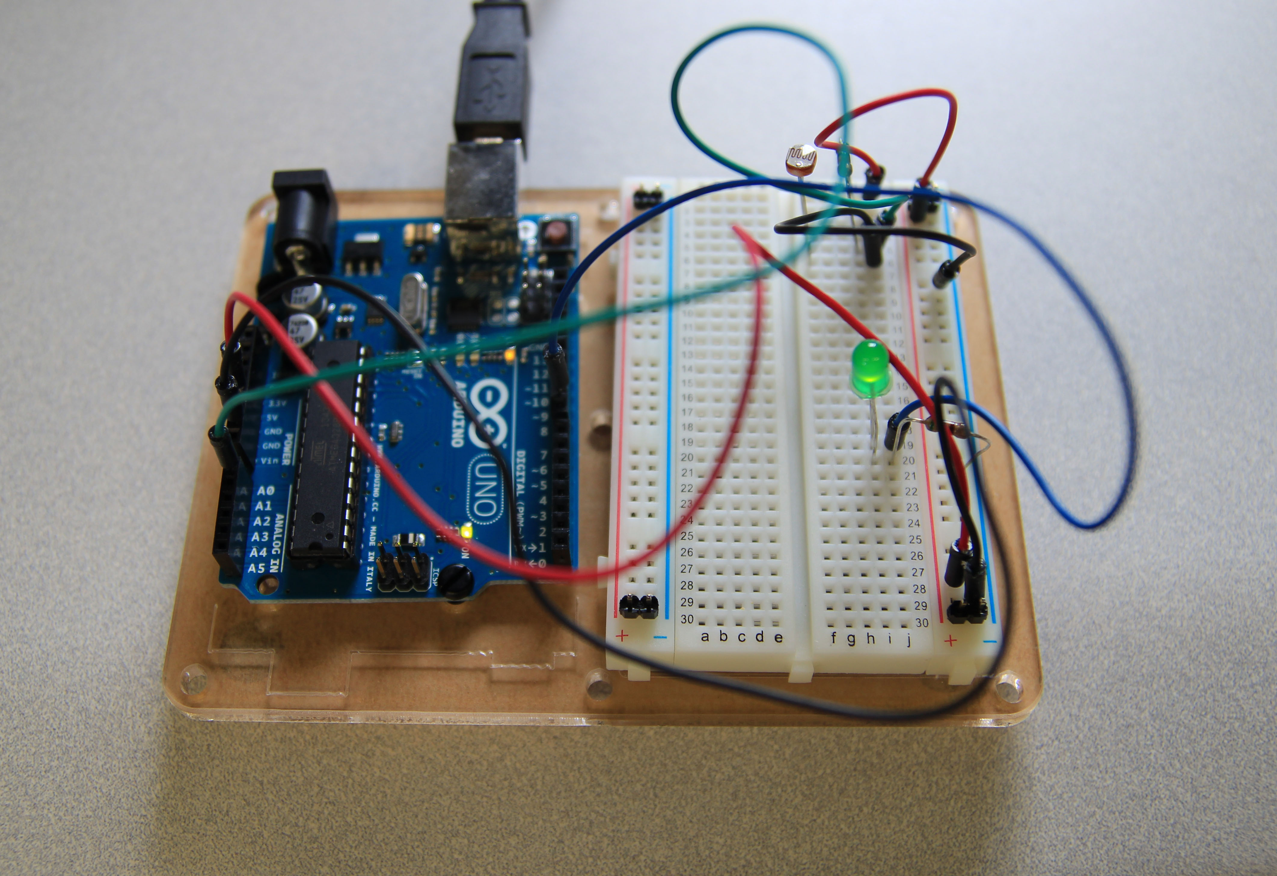 I found it useful that the instructions for building CRIC-9 (the photoresistor) showed multiple views of the components’ place on the breadboard. I now understand why each of the columns and rows have their own designation. The only point of frustration was that the wires kept getting in the way of the smaller components, in both assembly and documentation.
 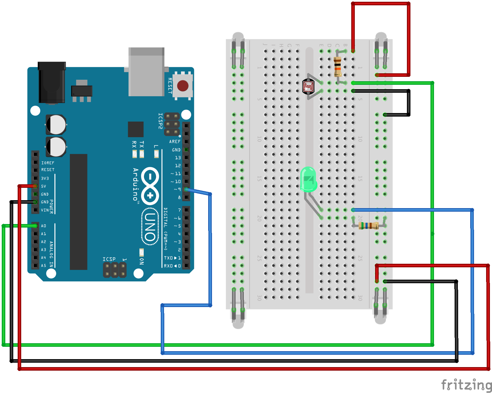 As for the Fritzing diagram, I’m not entirely sure if I used the proper object for the two-pin headers (and I’m still not entirely sure what they do), but the process of creating the diagram is straightforward, if a bit tedious.
/*
 * A simple programme that will change the intensity of
 * an LED based  * on the amount of light incident on
 * the photo resistor.
 *
 */

//PhotoResistor Pin
int lightPin = 0; //the analog pin the photoresistor is
                  //connected to
                  //the photoresistor is not calibrated to any units so
                  //this is simply a raw sensor value (relative light)
//LED Pin
int ledPin = 9;   //the pin the LED is connected to
                  //we are controlling brightness so
                  //we use one of the PWM (pulse width
                  // modulation pins)
void setup()
{
  pinMode(ledPin, OUTPUT); //sets the led pin to output
}
 /*
 * loop() - this function will start after setup
 * finishes and then repeat
 */
void loop()
{
 int lightLevel = analogRead(lightPin); //Read the
                                        // lightlevel
 lightLevel = map(lightLevel, 0, 900, 0, 255);
         //adjust the value 0 to 900 to
         //span 0 to 255


 lightLevel = constrain(lightLevel, 0, 255);//make sure the
                                           //value is betwween
                                           //0 and 255
 analogWrite(ledPin, lightLevel);  //write the value
}