Circuit #9 – The Photoresistor
The code as seen in the ARDX Kit book:
/*
  * A simple programme that will change the intensity of
  * an LED based  * on the amount of light incident on
  * the photo resistor.
  *
  */

//PhotoResistor Pin
int lightPin = 0; //the analog pin the photoresistor is
                  //connected to
                  //the photoresistor is not calibrated to any units so
                  //this is simply a raw sensor value (relative light)

//LED Pin
int ledPin = 9;   //the pin the LED is connected to
                  //we are controlling brightness so
                  //we use one of the PWM (pulse width
                  // modulation pins)
void setup()
{
  pinMode(ledPin, OUTPUT); //sets the led pin to output
}

/*
 * loop() - this function will start after setup
 * finishes and then repeat
 */
void loop()
{
  int lightLevel = analogRead(lightPin); //Read the
                                         // lightlevel
  lightLevel = map(lightLevel, 0, 900, 0, 255);
        //adjust the value 0 to 900 to
        //span 0 to 255

  lightLevel = constrain(lightLevel, 0, 255);//make sure the
                                             //value is between
                                             //0 and 255
  analogWrite(ledPin, lightLevel);  //write the value
}
Here is the video of the working circuit:
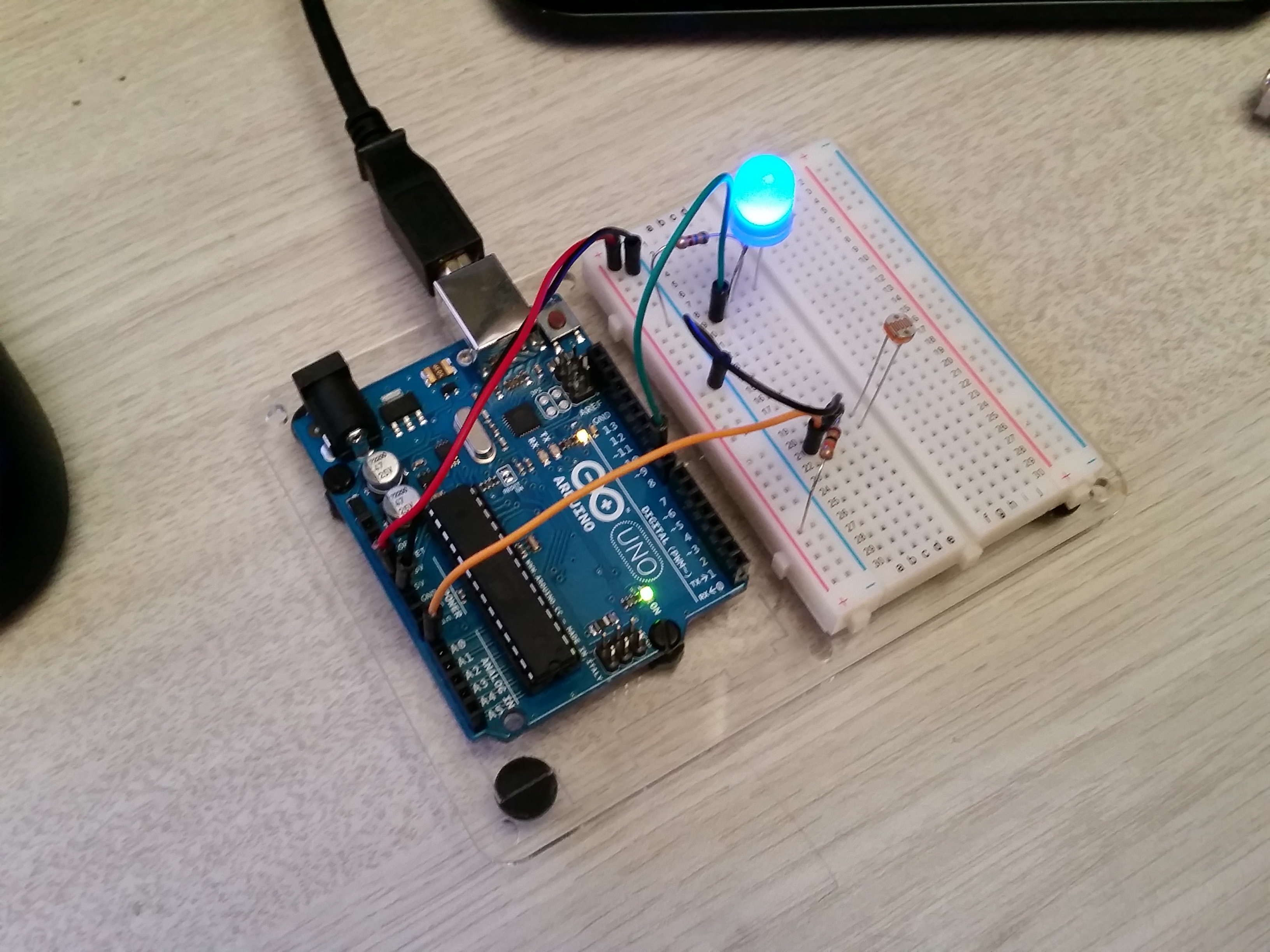
Here is a picture:
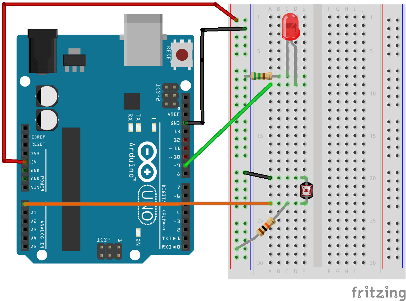
Here is a fritzing diagram: