SubFabricator
“How to Sculpt an Elephant: A Foolproof Method
Step one: Obtain a very large block of marble.
Step two: Remove everything that does not look like an elephant.”
– from comments on project sketch
Introduction:
Sub-Fabricator is a framework that enables Processing users to fabricate objects as the output of their Processing codes. The goal of Sub-Fabricator is providing a simple way for Processing users to exhibit their code outputs in form of fabricating prototypes through connecting Processing and Rhino GrassHopper while enabling users to create their desired forms in an interactive or a static way.
More Details:
Taking advantages of both, Sub-Fabricator provides a link between Processing and Grasshopper. Processing users can use Sub-Fabricator by implementing sub-fabricator interface for writing their code. They should provide Sub-Fabricator their code as a class which creates a set of drill paths for CNC router or milling robot. Then they can statically preview the output of their code or interactively create outputs in Sub-Fabricator user interface, which also runs in Processing. After adjusting their desired parameters for fabrication in Sub-Fabricator interface, they can send their desired output to GrassHopper. Additionally, they can, simply, tweak the outputs in GrassHopper Sub-Fabricator definition. From GrassHopper, users can send their file for fabrication.
Sub-Fabricator supports these features:
– Creating drill points or milling paths for one layer and multiple layer fabrication
– Interactive creation of drill points or milling paths
– 3d Environment for previewing outputs in Processing
– One sided and double sided milling or drilling
– Tessellating outputs on surfaces
You can find project:
Examples:
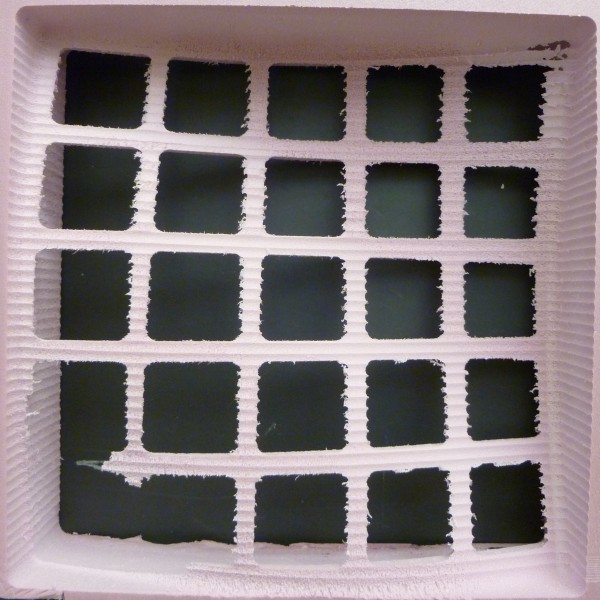
1- Sine wave with a grid of openings:
Processing Code:
UserClass3(int numInXDir, int numInYDir, float stepSize) { this.numInXDir = numInXDir; this.numInYDir = numInYDir; this.stepSize = stepSize; float maxDis = numInXDir * numInXDir + numInYDir * numInYDir; for (float x = 0; x <= numInXDir; x += stepSize) { for (float y = 0; y <= numInYDir; y += stepSize) { PVector position = new PVector(x, y, 60 + 40 * sin(map((x+y) / (numInXDir + numInYDir), 0 , 1, 0, 2 * PI))); float magnitude = ((x % 20 < 4 || x % 20 > 16) || (y % 20 < 4 || y % 20 > 16) ? 20 * sin(map((x+y)/ (numInXDir + numInYDir), 0 , 1, 0, PI)) : 0); float diameter = 1; CNCOneLayerData curData = new CNCOneLayerData(position, magnitude, diameter); COLData.add(curData); } } } |
Fabrication Image:
Fabrication Video:
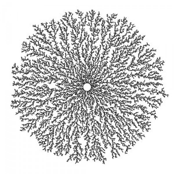
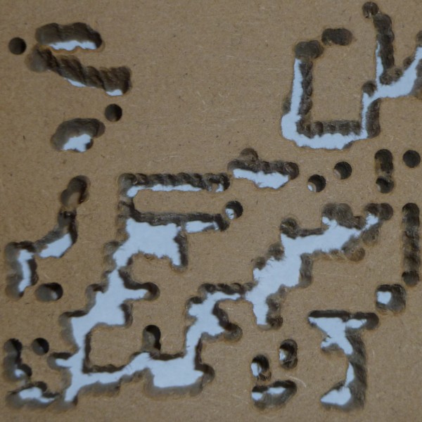
2- Diffusion Limited Aggregation Image:
Processing Code:
UserClass2() { // enter path to your image here img = loadImage("C:\\temp\\images\\wdrop.jpg"); this.numInXDir = img.width; this.numInYDir = img.height; this.stepSize = 10; int cols = floor(this.numInXDir / stepSize); int rows = floor(this.numInYDir / stepSize); for (int i = 0; i < cols; i++) { for (int j = 0; j < rows; j++) { float x = i * stepSize + stepSize / 2; // x position float y = j * stepSize + stepSize / 2; // y position int loc = floor(x + y * numInXDir); // Pixel array location color c = img.pixels[loc]; // Grab the color // Calculate a z position as a function of mouseX and pixel brightness float z = (brightness(img.pixels[loc])) / 255 * 10; PVector position = new PVector(x, y, 20); float magnitude = z; float diameter = 1; CNCOneLayerData curData = new CNCOneLayerData(position, magnitude, diameter); COLData.add(curData); } } } |
Original Image: (a small portion of this image fabricated)
Fabrication Image:
Fabrication Video:
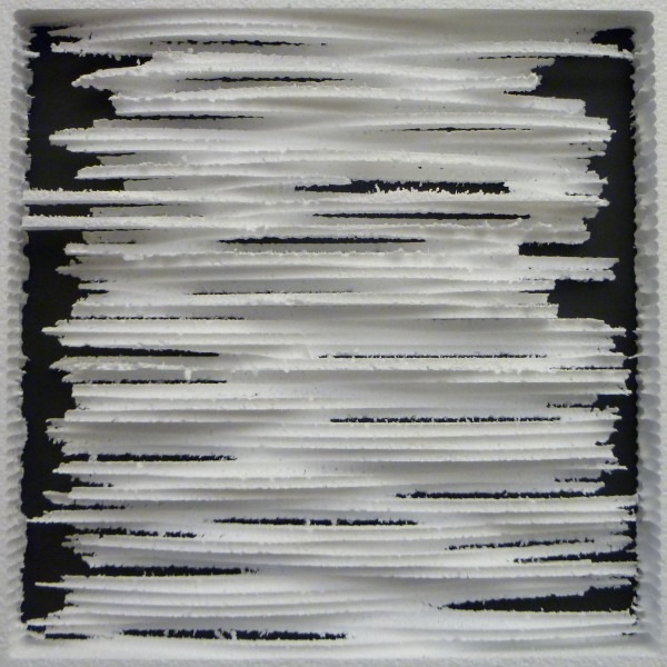
3- Random sine waves:
Processing Code:
UserClass5(int numInXDir, int numInYDir, float stepSize) { this.numInXDir = numInXDir; this.numInYDir = numInYDir; this.stepSize = stepSize; for (float x = 0; x < numInXDir; x += stepSize) { int randStart = (int) random(0, 100); for (float y = 0; y < numInYDir; y += stepSize) { float z = 15 + 5 * sin(map((y - randStart), 0, 100, 0, 2 * PI)) ; PVector position = new PVector(x, y, z); float magnitude = 10 * sin(map(y/ (numInYDir), 0 , 1, 0, PI)); float diameter = 1; CNCOneLayerData curData = new CNCOneLayerData(position, magnitude, diameter); COLData.add(curData); } } } |
Fabrication Image:
Fabrication Video:
What I Have Learned:
Working on this project I learned:
1- Lot about fabrication. Most important one is that milling is much, much faster and safer than drilling a point. While drilling DLA image I broke two drilling bits. Fabricating the small DLA image takes an hour while fabricating others take one hour totally (the change of material from wood to foam was helpful to some extents. I tested milling on MDF as well, it was much faster than drilling MDF. )
2- How to work with hash sets and tables.
3- Some data handling algorithms.
Challenges:
While writing codes and creating prototypes for demonstrating SubFabricator functionality, I have encountered many problems and challenges:
1- Checking if a form can be created even by a simple idea like drilling a bunch of points is a complicated problem, since every time a path milled or a point drilled the remain material changes and it may not be stable anymore for further fabrication, as an example think of fabricating a sphere.
2- Creating molds which are functional, usable, and stable and checking for all of these features needs considering many situations and exceptions. For example, questions like “Is all spaces connected?” and ”Do molds stay stable after casting?” come to the mind.
3- Creating reusable molds for complex shapes is an open problem.
4- Figuring out if a path is valid for milling using a 7 axis robot is mind blowing.
5- Implementing algorithms which has low run-time complexity for doing all data handling and problem solving is still a big challenge.
To Be Continued:
Current code just supports creating one layer form using CNC router. The complete project will support CNC multilayer and Robot one layer/multilayer forms as well. It also works based on drill points, this will changed to milling paths for sake of faster and safer fabrication. In addition, my final goal is providing a script writing environment for SubFabricator, where users can write and run their interactive codes in Processing language.


